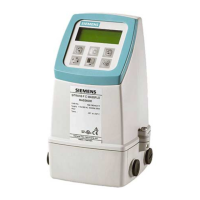
SITRANS FUH1010 Quick Start
Operating Instructions (Compact), 12/2008, CQO:QSG010 Revision A
39
Appendix A
A
A.1 I/O Connections and Wiring
Terminal Block Wiring
(Refer to manual drawing 1010XS2-7 sheet 3 of 3. When Barriers are used, isolation is
limited to the Barrier's working voltage. Refer to table on manual drawing 1010-341 sheet 3).
These connection diagrams apply to the part numbers listed below.
Table A- 1 Part Numbers and Connection Diagrams
1010XS2-7 (Sheet 3 of 3) Drawing
FUH1010 7ME3601ab
where:
a= 0
b= D or F
81/2&.
/2&.
7%
7%
*1'
6/
-
9
9
9
① Menu Lockout Switch S1
Table A- 2 FUH1010 Input/Output Wiring (TB1)
Pin# Signal Function Description
1
2
Not used on Single channel units.
3 Io1 - Isolated Loop Return
4 Io1 + Isolated Loop Supply
Spannable 4-20mA output proportional to any
available data variable assigned under menu
control.
5 ANIN - Analog Input Return
6 ANIN + 4-20mA Input
4-20mA input non-isolated (7ME3531-xF only)
7 Status - Status Bit Return Isolated Status Alarm Emiter
8 Status + Status Output Isolated Status Alarm Collector
9 PGEN - Pulse Generator Return Isolated PGEN Emitter
10 PGEN + Pulse Generator Output Isolated PGEN Collector

 Loading...


