SFIDK.PS.029.E5.02 / SW 2.01.07
13
3.5.1 Electrical connection - transmitter to transducers (1-track)
3.5 Electrical connection of the sensors / transducers
Note
When the terminal box is disassembled, the wires (2 and 3) must be loosened from the
connection board. It is not necessary to remove the transducer cables (1 and 4).
Support the terminal box while loosening the union. Then remove the terminal box from the
transducer holder.
Warning
Twisting the terminal box can damage the wires to the crystals.
Warning
According to the "Ex-requirements", the 'PE-terminals' on the FUS060 and on the sensors
(SONO 3200 transducers or SONO 3300 sensor) must be potential equalised (min. 4 mm
2
).
Warning
The PE-terminals should always be connected to solve EMC problems (Ex-Version on non Ex).
Flow direction
The connection of the terminal housing of sensor type SONO 3300 is described in the separate sensor
operating instructions.
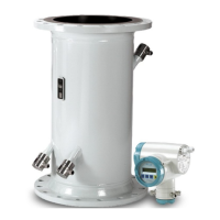
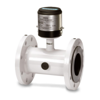
The sensors type SONO 3100 and SONOKIT consist of a sensor pipe and 2 / 4 ultrasonic transducers
type SONO 3200. The terminal housing is fastened to the transducer holder by means of a union. Avoid
stress on the two inner wires when transferring them into the terminal housing, . The wire without a
thimble is connected to position 2. The wire with a thimble is connected to the transducer housing by
means of position 3. The inner wire of the transducer coax cable is fastened with the cable lamp into
position 4. The transducer cables can be shortened at the respective transducer end (not at the high
temperature versions). In this case, the cable length must be corrected in the FUS060 (menu 7).

 Loading...


