SDS Series
50
FAULT FINDING THE CONTROLLER:
SDS Series controllers have been designed for simplified service and repair. The controller
does not require a service technician for on-site electronic repair - instead utilising plug-in
replacement PCB modules.
The principle components of the controller consist of:
1. A mother board which contains the internal PCB power supply, lightning protec-
tion and plug-in module interfaces.
2. A plug-in logic board which houses the microcontroller, timing clock and system
memory
3. A plug-in output board which drives the two-wire network.
4. A plug-in keypad assembly which incorporates the display.
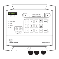
Page 51 of this manual indicates the various key components and also the LED indictors and
their normal status. These are used to initially pinpoint the fault condition if they display ab-
normal.
Fault Finding
ROUTINE THINGS TO CHECK FIRST:
1. Is the power switched on at the controller.
2. Test the power supply to the controller with a DC volt meter. It should read 36VDC
3. Check that the terminal strip is not loose
4. Check that the terminal screws are firm but not over tight
5. Check that the wires have not pulled away from the terminal strip by lightly pulling
on them
6. Check the current draw at the controller INFORMATION menu. Normal current
draw for each DataCoil model is as follows:
SD2NC: Idle = 1.5 mA | Running = 16 mA
SD3NO: Idle = 1.5 mA | Running = 21 mA
SD3LT: Idle = 1.5 mA | Running = 1.5 Ma
If these steps are unsuccessful, try resetting the controller to factory default settings.
Try re-setting the controller to factory default setting, then reprogram..
REPLACING THE PLUG-IN MODULES:
Refer to next page for correct PCB LED indictors.
Before any module is replaced, turn the power off to the controller. Always hold the modules
at the edge of the PCB boards. Modules are designed to easily plug in so no force is required.
Make sure the connectors are aligned and no problems will be encountered. It is often easier
when replacing the logic board to unplug the key board display panel to provide easier ac-
cess.
Do not over tighten the four retaining screws at each corner when securing the key pad back
in place, just lightly nip the screws up to the panel.
The motherboard has 7 screws locating it to the base of its enclosure, make sure all are re-
moved when replacing the board and it will lift away easily.
 Loading...