SDS Series
51
Fault Finding
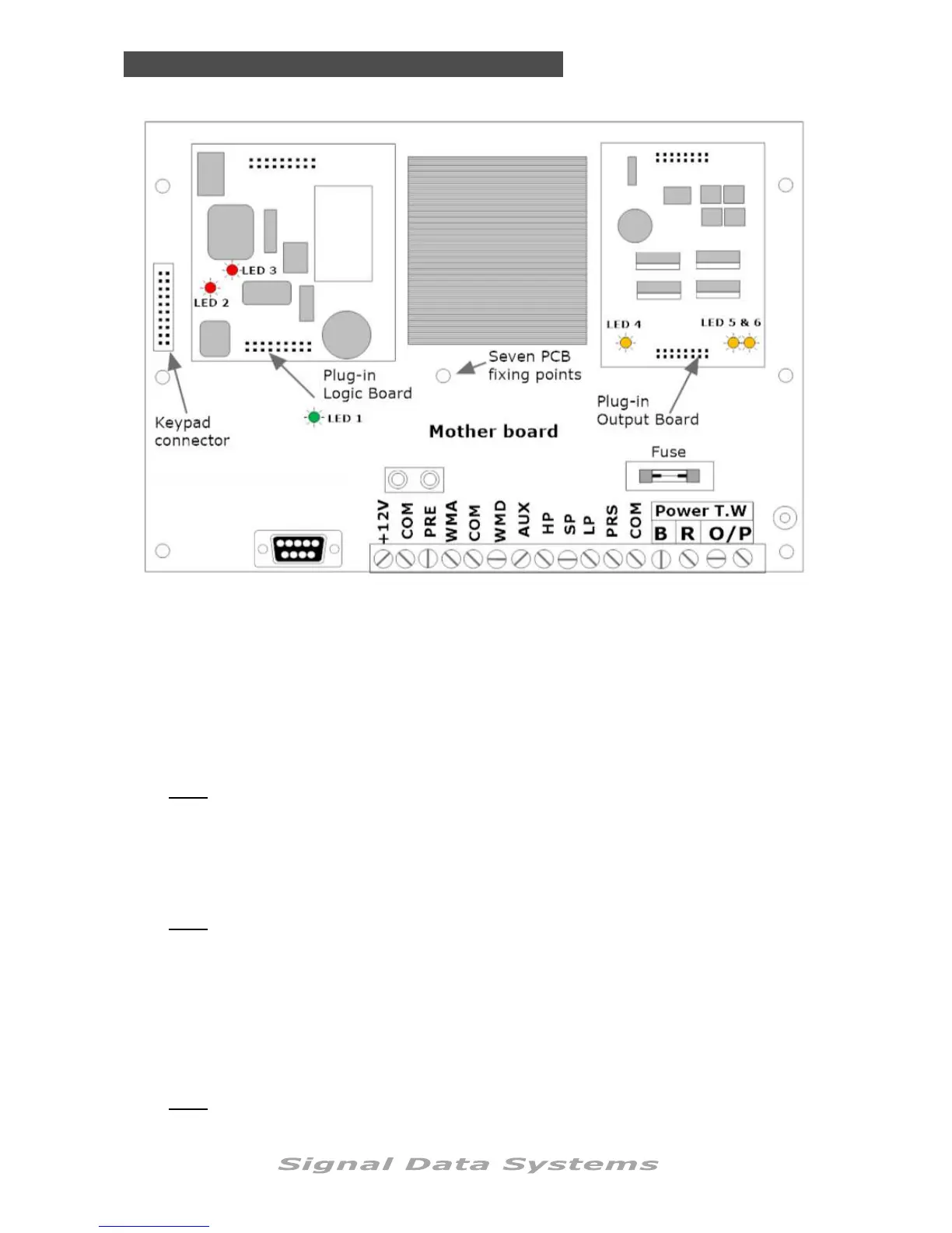
2. If LED 1 is on, proceed to LED 2 and 3.
LED 2 should be on, LED 3 should flash. If not correct on both LEDs, replace the plug-
in logic module.
Note: LED 2 indicates power to the Logic module LED 3 indicates the microprocessor
timers are working.
3. If LED 1, 2 and 3 are all correct proceed to LEDs 4 , 5 and 6.
This test assumes all other LEDs are normal.
LED 4 should be on. Press any key at the keypad and LED 5 and 6 should activate. If
this is not correct, replace the plug-in output module.
Note: LED 4 indicates power to the output board, LED 5 and 6 indicate power out from
the output module.
If it is suspected a fault is present at the controller and not in the field cabling or DataValves,
proceed as follows:
1. Remove the four front keypad panel screws and carefully lift to one side, press any
key on the keypad to ensure the output is switched on. Observe the six LEDs for
correct operation.
LED 1 should be on. If it is not, test for DC voltage at B R terminals. If this is OK, re-
place the mother board.
Note: LED 1 indicates normal operation of the PCB motherboard power module.
 Loading...