Functional Description
AP04-RS485/SIKONETZ5
Date: 24.11.2016 Art. No. 86218 Mod. status 351/16 Page 8 of 38
3.3 Loop positioning
The LED display refers always to the actual set point, not to the loop value.
Target window1 is also applied to the loop length.
If the position indicator is operated on a spindle or an additional gear, the spindle or external
gear backlash can be compensated by means of loop positioning. In this case, travelling to
the target value is always from the same direction. This direction of approach can be defined.
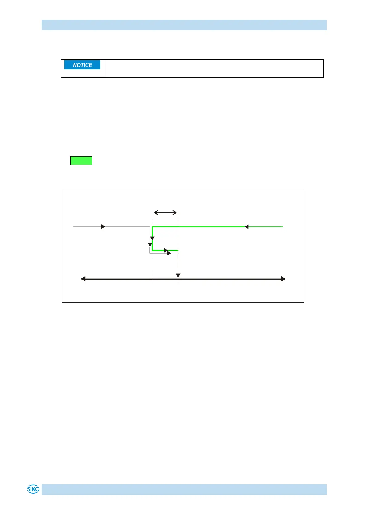
Example:
The direction from which every target position shall be driven to is positive.
Case 1 new position is greater than actual position:
Direct travel to the target position.
Case 2 new position is smaller than actual position:
The position indicator's arrows show that the set point is to be overrun by the loop length.
Afterwards, the set point is approached in positive direction.
Fig. 3: Positioning Loop +
Positioning in positive
direction
Positioning in negative
direction
 Loading...