SC
A6
MD
MB
M
DB
B9
B10/70/4
B3
B2
H1
TA*
SE
F1
Q1
Q3/y3
L
N
N
L
ALBATROS RVA43.222
PI
E1
K5
F5
K4
F4
Verso comandi accensione
I° e II° stadio bruciatore
vedere schema elettrico caldaia
*Qualora non vi sia un termostato ambiente,
predisporre un ponte permanente
Il collegamento elettrico va eseguito
all'interno del pannello comandi della caldaia.
Per i dettagli consultare lo schema
elettrico della caldaia
TM
PBY
L
N
Per le pompe vedere i morsetti di appoggio in caldaia
PB
SB
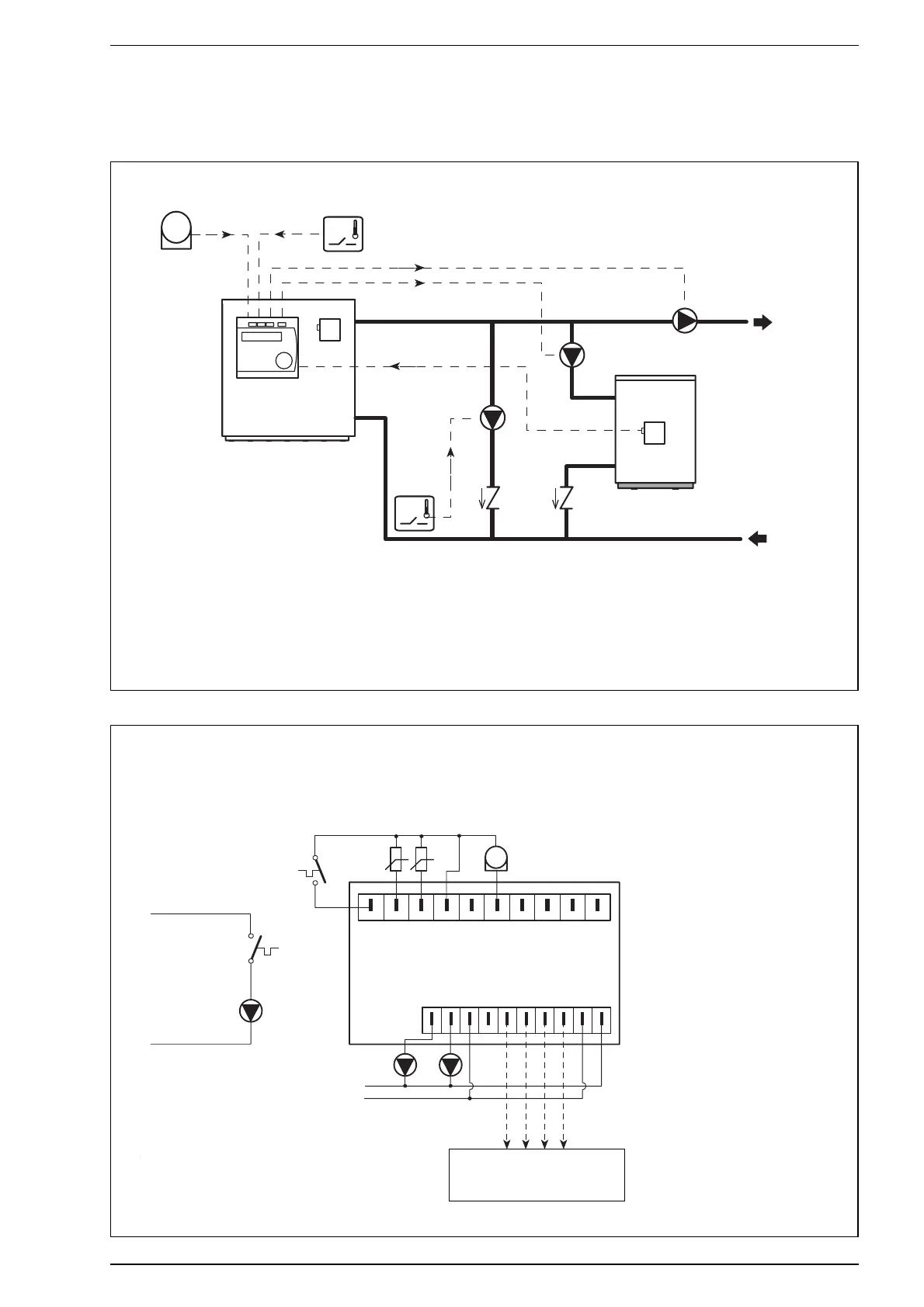
3.4.1 SYSTEM I2 - boiler with external hot water tank
Hydraulic circuit
LEGEND
SC Boiler delivery probe (QAZ21)
SE Outdoor temperature probe
(QAC31)
SB Hot water tank probe (QAZ21)
PI Boiler pump
TA Room thermostat
PBY Bypass pump
TM Minimum return thermostat
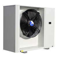
Wiring diagram
LEGEND
SC Boiler delivery probe (QAZ21)
SE Outdoor temperature probe (QAC31)
SB Hot water tank probe (QAZ21)
PI Boiler pump
PB Hot water tank pump
TA Room thermostat
PBY Bypass pump
TM Minimum return thermostat
HOT WATER TANK
(separate)
BOILER
*If there is no room thermostat, set up
a permanent jumper
Wiring must be performed inside the boiler’s con-
trol panel. For details please refer to the boiler’s
wiring diagram.
For pumps, refer to supporting terminals on the boiler
Toward burner stage 1 and 2
ignition commands. Refer to boiler
wiring diagram.