96
ZONE 3: mixer valve, pump, zone probe, overheating thermostat
and room temperature control unit (floor system)
(refer to RVA46.531series D manual)
System identification
–
Setting mode = USER
(refer to section on parameter setting levels
)
–
Setting mode = INSTALLER
(refer to section on parameter setting levels)
Note 1: The overheating thermostat stops heat production if water
temperature is too high and threatens to damage the floor. It should
be set to around 45°C.
Note 2: If there are only two boilers, the first RVA46 control will have
device address 3, the second RVA46 controller will have device
address 4, and so on.
3.7.3 Checking for correct recognition
To check that the controller has correctly recognised the type of
system on the basis of the parameters entered, display the installer
parameter in row 53. For the MASTER, system n. 8 should appear;
for SLAVES 1 and 2, system n. 9.
For zones display the installer parameter RVA46.531 in row 53. For
the ZONE 1, system n°11should appear,For the ZONE 2, system
n°112 and For the ZONE 3, system n°11.
Note: Where there are more than three zones, each of which is con-
trollled by the unit RVA46.531, the parameterization is the same and
in increasing order with the addresses of the LPB apparatus. If a num-
ber external temperature sensors are to be attached (apartments
that are more or less exposed to the sun) connect them to the
RVA46.531 unit, taking into account that the signal is propagated
towards the higher LPB apparatus addresses.
4 FUNCTIONAL TESTS
Once the controller has been installed with the required electrical
connections, it is a good idea to check the configuration by testing
inputs and outputs in order to identify any malfunctions or faults
immediately.
Output tests
This test checks all outputs before start-up.
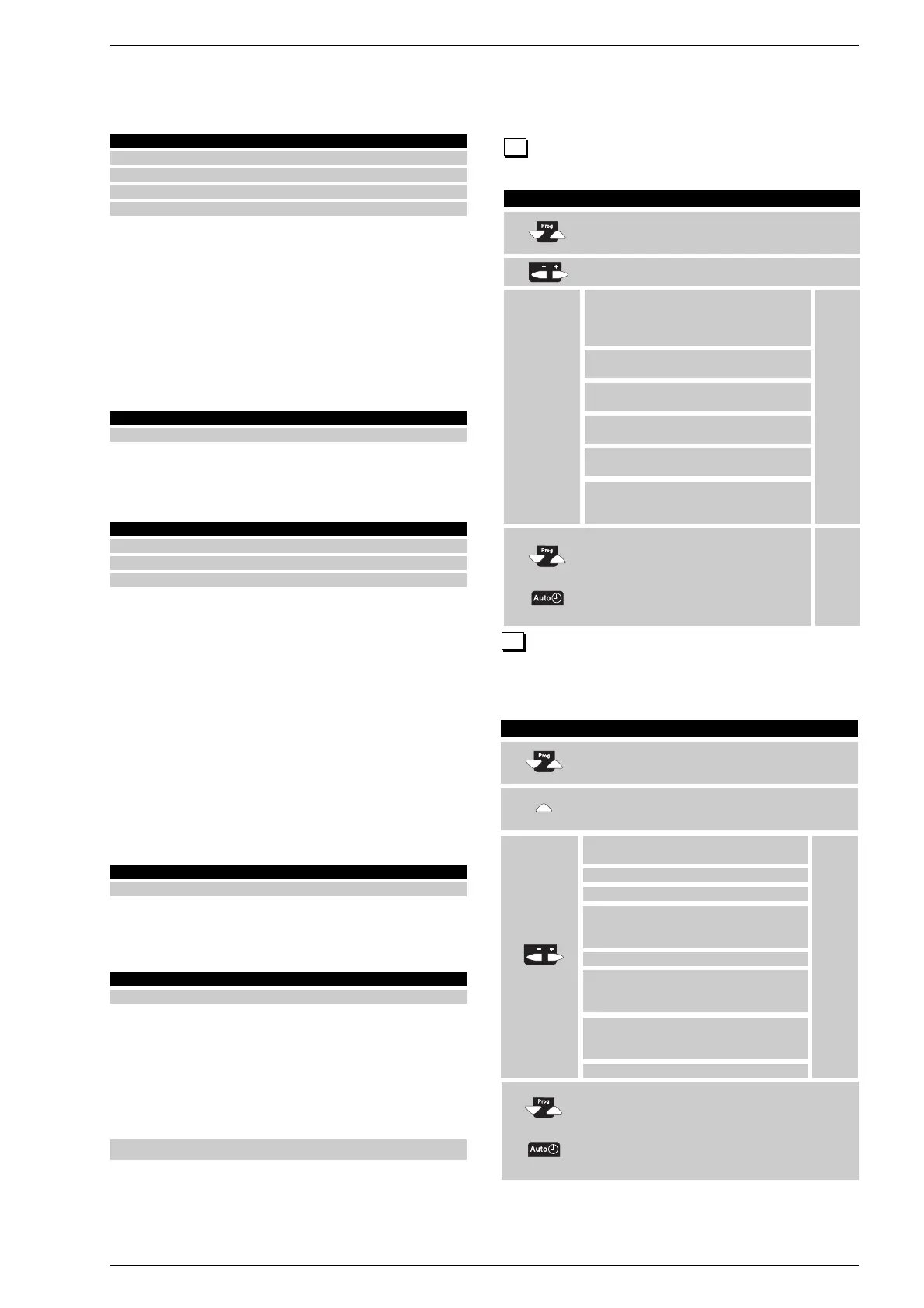
Input tests
This test, also referred to as probe test, checks wiring and sensor
configurations.
Notes
––– = sensor open or not connected
°°°= sensor short-circuited
52
Button Explanation Row
PRESS BOTH ROW SELECTION PUSHBUTTONS
1 FOR AT LEAST 3 SECONDS. THIS WILL 51
TAKE YOU TO PROGRAMMING MODE
PRESS THE “UP” SELECTION BUTTON UNTIL YOU
2 REACH ROW 52. THIS WILL TAKE YOU TO 52
THE INPUT TESTS
PRESS THE PLUS OR MINUS BUTTON REPEATEDLY
TO MOVE ONE STEP AT A TIME
3 52
TO EXIT PROGRAMMING MODE AND THE INPUT
TEST, PRESS ONE OF THE OPERATING MODE
BUTTONS.
4
If no buttons are pressed for about
8 minutes, the controller will automatically
return to the last operating
mode selected.
TEST STEP 0
TEST STEP 1
TEST STEP 2
TEST STEP 3
TEST STEP 4
TEST STEP 5
TEST STEP 6
BOILER TEMPERATURE (B2)
HOT WATER TEMPERATURE (B3)
TEMPERATURE OF PROBE
SELECTED AT ROW 96
(B10/70/4)
OUTDOOR TEMPERATURE B9
ROOM TEMPERATURE ACQUIRED
WITH ROOM UNIT CONNECTED
TO A6
INPUT H1 ACCORDING TO
FUNCTION SELECTED ON ROW
170 (°C o “°°°” o “–––”)
INPUT E1(“°°°” o “–––”)
Button Explanation Row
PRESS BOTH ROW SELECTION PUSHBUTTONS
1 FOR AT LEAST 3 SECONDS. 51
THIS WILL TAKE YOU TO THE OUTPUT TESTS
PRESS THE PLUS OR MINUS BUTTONS
2
REPEATEDLY TO MOVE ONE STEP AT A TIME
51
TO EXIT PROGRAMMING MODE AND THE
OUTPUT TEST, PRESS ONE OF THE
OPERATING MODE BUTTONS.
3
If no buttons are pressed for about
8 minutes the controller will automatically
return to the last operating
mode selected.
TEST STEP 0
TEST STEP 1
TEST STEP 2
TEST STEP 3
TEST STEP 4
TEST STEP 5
ALL OUTPUTS PERFORM
SWITCHING IN
ACCORDANCE WITH
THE CONTROL MODE
ALL OUTPUTS
ARE OFF
BURNER STAGE 1 (K4)
ACTIVATED
BURNER STAGE 1 + 2 (K4 +
K5) ACTIVATED
HOT WATER TANK PUMP/THREE-
WAY VALVE (Q3/Y3) ACTIVATED
HEATING CIRCUIT BOILER
PUMP OR PRIMARY PUMP
(Q1) ACTIVATED
51
Permanent
display
Permanent
display
Par Description Default values Setup
67 Differential on room temp. intervention time –.–– 1
69* Setpoint of d.h.w. temperature 80 70
85 LPB device address 0 5
87 Clock mode 0 2
*Depending on type of system
Par Description Default values Setup
17* Slope of heating curve 15 7, 5
*Depending on type of system
Par Description Default values Setup
69* Setpoint of d.h.w. temperature 80 37
85 LPB device address 0 6
87 Clock mode 0 2
*Depending on type of system
Par Description Master Slave 1 Slave 2
53 Display of plant type 89 9
Par Description Zone 1 Zone 2 Zone 3
53 Display of plant type 11 12 11
 Loading...