Il collegamento elettrico va eseguito
all'interno del pannello comandi della caldaia.
Per i dettagli consultare lo schema elettrico
della caldaia
Per le pompe vedere i morsetti di appoggio in caldaia
RLn
TAn
RL1
TA1
N
L
SC
A6
MD
MB
M
DB
B9
B10/70/4
B3
B2
H1
SE
F1
Q1
Q3/y3
L
N
N
L
ALBATROS RVA43.222
P1
E1
K5
F5
K4
F4
Verso comandi accensione
I° e II° stadio bruciatore
vedere schema elettrico caldaia
SM
CRL1
CRLn
SC
A6
MD
MB
M
DB
B9
B10/70/4
B3
B2
H1
F1
Q1
Q3/y3
L
N
N
L
ALBATROS RVA43.222
E1
K5
F5
K4
F4
Verso comandi accensione
I° e II° stadio bruciatore
vedere schema elettrico caldaia
SR
SC
A6
MD
MB
M
DB
B9
B10/70/4
B3
B2
H1
F1
Q1
Q3/y3
L
N
N
L
ALBATROS RVA43.222
E1
K5
F5
K4
F4
Verso comandi accensione
I° e II° stadio bruciatore
vedere schema elettrico caldaia
–+ –+
–+
LPB BUS Non invertire la polarità della connessione
PZ1
PZn
C
2
1
TMIN
MASTER
SLAVE 1
SLAVE 2
P3
P3
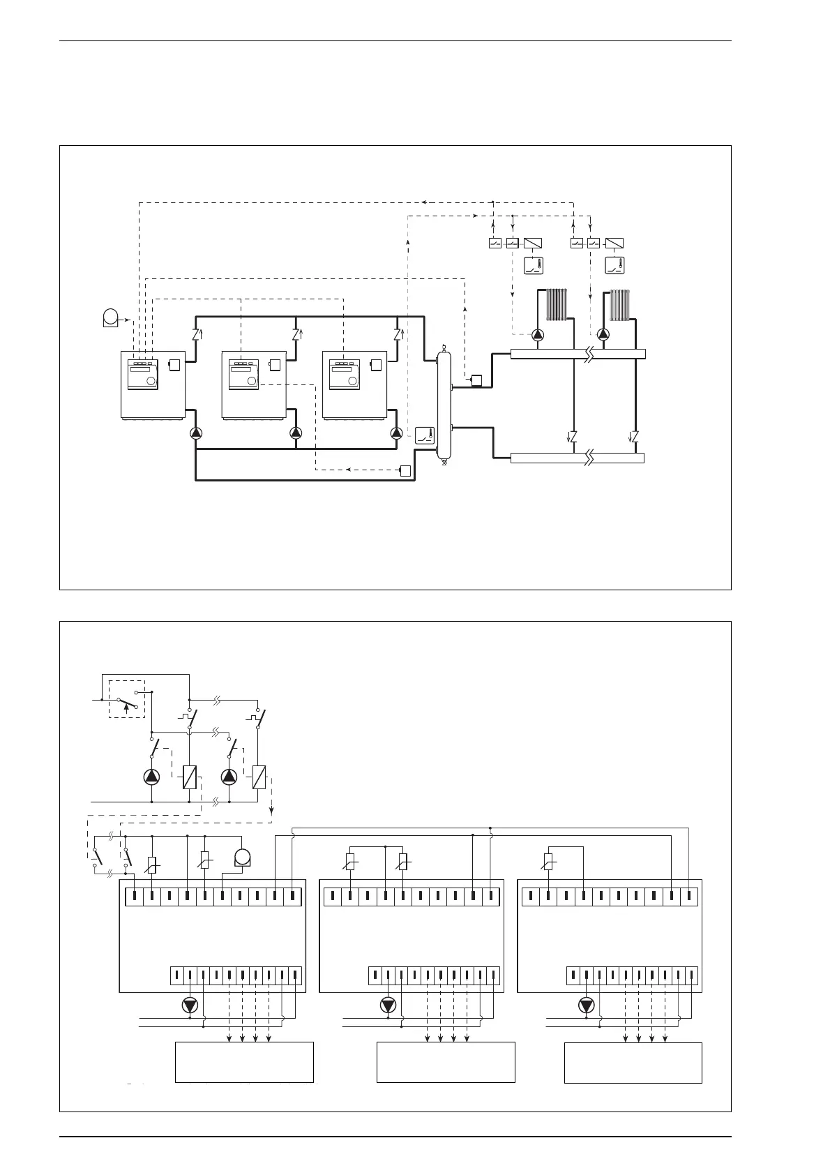
3.5.2 SYSTEM I4 - 2/3 boiler cascade for heating only with zone pumps
Hydraulic circuit
LEGEND
SM Cascade delivery probe (QAD21)
SE Outdoor temperature probe (QAC31)
SI Hydraulic separator
SR Cascade return probe (QAD21)
PI
1-2-3 Boiler pumps
SC Boiler delivery probe (QAZ21)
VZ
1-n Zone pumps
TA
1-n Room thermostats
RL
1-n Dual contact zone relays
TMIN Minimum cascade
return thermostat
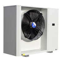
Wiring diagram
LEGEND
SM Cascade delivery probe (QAD21)
SE Outdoor temperature probe (QAC31)
SR Cascade return probe (QAD21)
PI
1-2-3 Boiler pumps
SC Boiler delivery probe (QAZ21)
PZ
1-n Zone pumps
TA
1-n Room thermostats
RL
1-n Dual contact zone relays
CRL
1-n Clean zone contacts
TMIN Minimum cascade return thermostat
Wiring must be performed inside the boi-
ler’s control panel. For details please refer
to the boiler’s wiring diagram.
Do not invert connection polarity
Toward burner stage 1 and 2 ignition
commands Refer to boiler wiring
diagram.
Toward burner stage 1 and 2 ignition
commands Refer to boiler wiring
diagram.
Toward burner stage 1 and 2 ignition
commands Refer to boiler wiring
diagram.
For pumps, refer to supporting terminals on the boiler