2.9.2 System volume (total water content)
The following table gives the maximum system volume that
the integral 7 l expansion vessel can sustain under different
charge pressure conditions.
If the system volume exceeds that shown, an additional
expansion vessel must be fitted and connected to the hea-
ting system primary return pipe as close as possible to the
appliance.
If an extra vessel is required, ensure that the total capacity
of both vessels is adequate. Further details are available in
the current issues of BS5449 and BS6798.
NOTE: If the pressure gauge indicates 2.65 bar or grea-
ter when the appliance is at maximum temperature
with all radiators in circulation an extra expansion
vessel is required.
2.9.3 Pressure gauge
A pressure gauge is mounted on the appliance facia panel.
2.9.4 Safety valve
A safety valve set at 3 bar (43.5 psi) is fitted to the
appliance and a discharge pipe is routed to outside of the
appliance.
This discharge pipe should be extended to terminate
safely away from the appliance and where a discharge
would not cause damage to persons or property but
would be detected.
The pipe should be able to withstand boiling water, be a
minimum of 15 mm in diameter, and not include any hori-
zontal runs prone to freezing.
2.10 D.H.W. SYSTEMS
– The authority of the local Water Company should be
obtained before the appliance is connected to the cold
water mains supply.
Check that the mains supply pressure is within the prescri-
bed limits (section 1.3).
If necessary, a pressure reducing valve should be fitted to
the mains supply before the D.H.W. inlet connection.
– The final 600 mm (24 in) of the mains supply pipe to the
boiler must be copper.
– A maximum D.H.W. flow rate of 10 l/m (2.2 gpm) is
recommended. Higher flow rates will not damage the
7
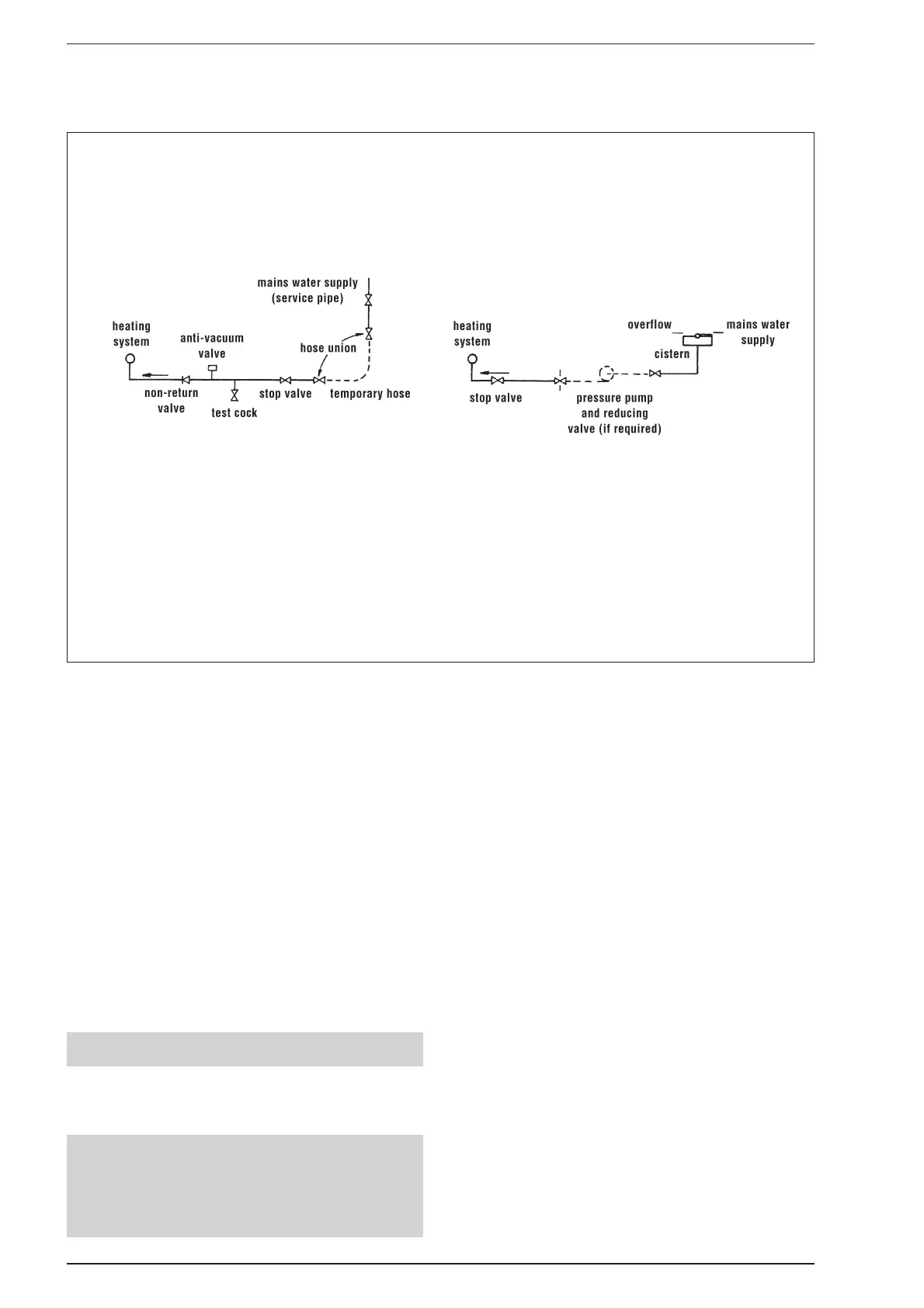
ALTERNATIVE METHODS OF FILLING A SEALED SYSTEM
NOTES:
– When it is not possible to avoid a situation where the initial system pressure and static head are equal a manually
fitted top up container should be fitted as shown above.
Take note of the requirements relative to container capacity: height above system, inclusion of a non-return valve,
stop cock and automatic air vent in the feed pipe, as shown in fig. 5.
Note also the feed pipe connection is made to the heating return as close to the appliance as possible.
– The Local Water Undertaking MUST approve ALL connections between the system and a water storage cistern or
water main supplying D.H.W.
METHOD 1 (complies with BS6798.1987)
METHOD 2 (complies with BS6798.1987)
Vessel charge and initial system
pressure
Total water content of system
using 7 l (1.54 gal) capacity
expansion vessel supplied with
appliance
For systems having a larger
capacity multiply the total
system capacity in litres (gallons)
by the factor to obtain the total
minimum expansion vessel
capacity required litres (gallons)
bar
psi
l
gal
0.5
7.3
87
18.5
.0833
1.5
21.8
44
9.7
.156
1.0
14.5
64
14.0
.109
TABLE 8
Fig. 6