– To replace electrode remove the control box cover, pull
off connection from the spark generator and work the
lead through the plastic grommet in the base of the
combustion chamber.
– Replace and reassemble in reverse order.
“FRIENDLY E” model
– Remove the combustion chamber front panel as descri-
bed in section 5.1.
– Unscrew electrode. TO REPLACE ELECTRODE ONLY.
Replace electrode, and go to last step.
– Remove the old pilot burner and replace with the new
one. Check that the critical dimensions are as shown in
fig 26.
–
Re-assemble in reverse order and check for gas soundness.
8.6 GAS VALVE
8.6.1 V4600C mounted on “FRIENDLY” model
– Remove the outer casing as described in section 5.1.
–
Disconnect the electrical connections to the gas valve by
removing grey cover (take out one screw), pulling wires
from connectors and disconnecting earth. Remove plug
from modulator coil by taking out screw and pulling clear.
– Unscrew the pilot pipe connector at the L.H.S. of valve.
Unscrew thermocouple from rear of valve. Take off
microswitch by removing screw.
– Unscrew the burner manifold union.
– Unscrew the four posi-head screws securing the gas
valve inlet pipe, and remove the gas valve complete with
the outlet pipe.
– Transfer the outlet pipe onto the new gas valve, using a
new gasket (supplied with the valve).
– Fit the new gas valve assembly into the appliance using
the other new gasket supplied on the valve inlet, and re-
assemble in reverse order.
–
Relight the appliance, check for gas soundness, and
recommission in accordance with section 4. In addition it
will be necessary to set the D.H.W. and C.H. heat inputs,
as follows (fig. 27).
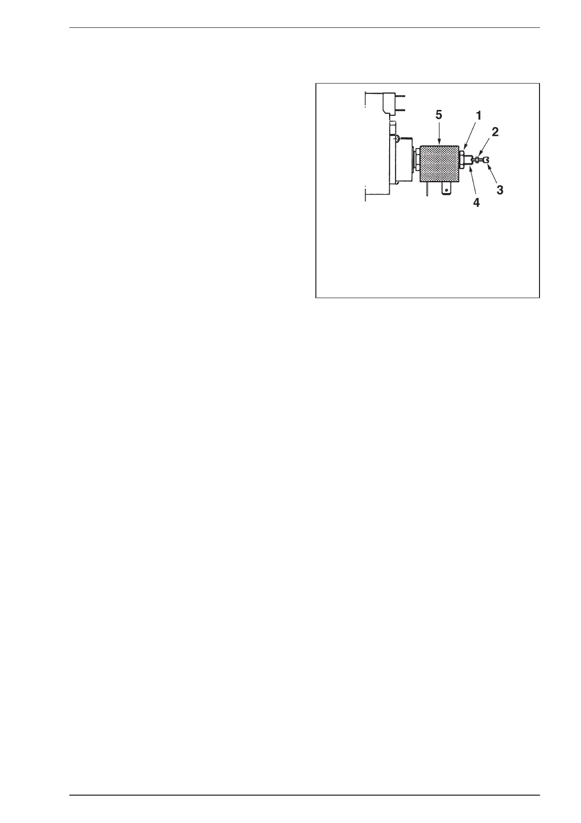
Disconnect one of the electrical connections to the coil
(5). Undo nut (2) and remove screw (3). Turn the D.H.W.
temperature adjuster (3 fig. 17) clockwise to maximum
and open the D.H.W. taps.
Undo nut (1) and turn stud (4) clockwise to increase the
pressure, and anti-clockwise to decrease the pressure,
until the correct pressure is reached.
Tighten nut (1) keeping stud (4) from moving using a
screwdriver. Check the burner pressure is stable. Close
the D.H.W. taps.
Set Summer/Winter switch to WINTER. Using a screwdri-
ver turn trimmer (2 fig. 17) fully anti-clockwise to maxi-
mum. Turn the C.H. temperature adjuster (1 fig. 17)
clockwise to maximum. Adjust the minimum pressure by
turning the minimum rate adjustment screw (3) clockwi-
se to increase the pressure, and anti-clockwise to decrea-
se the pressure, until the correct pressure is reached.
Tighten locking nut (2) without rotating screw (3). Check
the burner pressure is stable. Turn the trimmer clockwise
to set the pressure for the required output. Remove pres-
sure gauge and tighten burner pressure test nipple.
Check for gas soundness with leak detector fluid.
– Continue as in section 4.3 to 4.5.
8.6.2
SIT 837 TANDEM mounted on “FRIENDLY E” model
– Remove the outer casing as described in section 5.1.
– Disconnect the electrical connections to the gas valve.
– Unscrew the pilot pipe connector.
– Unscrew the burner manifold union.
– Unscrew the four posi-head screws securing the gas
valve inlet pipe, and remove the gas valve complete with
the outlet pipe.
– Transfer the outlet pipe onto the new gas valve, using a
new gasket (supplied with the valve).
– Fit the new gas valve assembly into the appliance using
the other new gasket supplied on the valve inlet, and re-
assemble in reverse order.
– Relight the appliance, check for gas soundness, and
recommission in accordance with section 4.
In addition it will be necessary to set the D.H.W. and
C.H. heat inputs, as follows:
– remove the sealing cap of the proportioning unit (C
fig. 28) by rotating it ⁄ turn anticlockwise;
– using a 10 mm spanner, turn nut (B fig. 28) to attain
11.1 mbar (4.4 inwg) of pressure. Turn the nut
clockwise to increase the pressure or anti-clockwise to
decrease it;
– check that the maximum pressure is correctly set by
turning on and off the D.H.W. inlet valve several times
and ensuring that the pressure returns to that pre-
viously adjusted;
– isolate the mains electricity supply and disconnect
(pull off) the two 24 V modulation leads. Restore the
mains supply. The appliance will light on minimum
input only;
– set the minimum pressure of 1.5 mbar by holding nut
(B fig. 28) in position with a 10 mm spanner and
rotating the plastic screw (A fig. 28) with a screwdri-
ver until the correct pressure is obtained.
Turn the screw clockwise to increase the pressure or
anti-clockwise to decrease it. It is essential that the
max pressure has been set prior to adjusting the mini-
mum pressure. Check that the minimum pressure is
correctly set by turning on and off the D.H.W. inlet
valve several times and ensuring that the pressure
returns to that previously adjusted;
26
KEY
1 Locking nut M7
2 Locking nut M2
3 Adjustement screw for
minimum pressure setting
4 Adjustement stud for
maximum pressure setting
5 Modulating coil with 6.3 mm AMP terminals
Fig. 27