12
3.7 GAS CONNECTIONS
– Screw the gas cock into the internal thread in the gas
inlet connection using a suitable jointing compound.
– Connect the gas supply pipe.
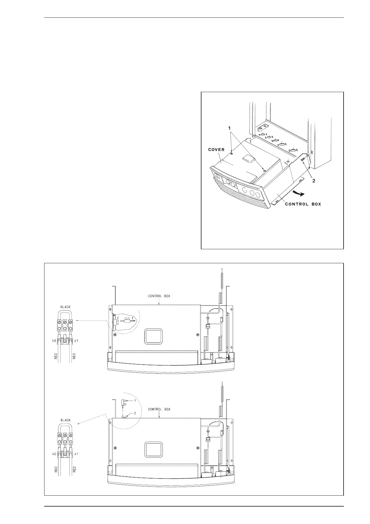
3.8 SAFETY VALVE CONNECTION
– The appliance safety valve is located towards the R.H.S.
of the boiler and the discharge pipe is supplied loose.
Remove the two screws TCB M4 x 10 (2 fig. 14) and
lower the control box to improve access.
– Screw the discharge pipe to the valve outlet using a sui-
table jointing compound, and extend the pipe to ensure
that any discharge from the safety valve is safely routed
to a drain. The discharge pipe should be a minimum of
15 mm copper, and should avoid sharp corners or
upward pipe runs where water may be retained.
3.9 WIRING INSTRUCTIONS
(Refer to sections 2.6 - 2.7)
The external wiring is connected to the boiler via a lead
cable situated behind the control box at the L.H.S.
– If a room thermostat is to be used, remove the link
between terminals 40 and 41 in the terminal provided
therein and replace it with the room thermostat.
– Carry out electrical system checks through a suitable
test meter: earth continuity, polarity, resistance to earth
and short circuit.
– Resecure control box.
KEY
1 3 pins socket
2 3 pins plug
KEY
1 Self tapping screw
2 Screw TCB M4 x 10
Fig. 14
Fig. 15
“FRIENDLY” model
“FRIENDLY E” model