24
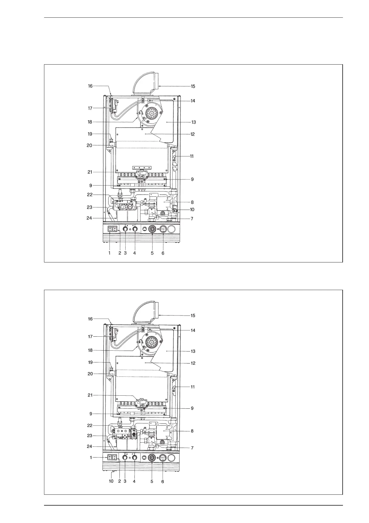
Fig. 24/a
7.3 INTERNAL VIEW “FRIENDLY” MODEL
KEY
1 Clock override switch
2 Summer/Winter switch
3 C.H. potentiometer
4 D.H.W. potentiometer
5 Clock
6 Pressure gauge
7 Divertor valve
8 Circulating pump
9 Burner manifold screws
10 Overheat thermostat
11 C.H. thermistor
12 Combustion chamber
13 Sealed chamber
14 Fan mounting plate screws
15 Air/flue elbow
16 Pressure switch bracket screws
17 Pressure switch
18 Fan
19 Limit thermostat
20 Heat exchanger
21 Pilot assembly
22 Gas valve
23 D.H.W. thermistor
24 D.H.W. heat exchanger
Fig. 24/b
7.4 INTERNAL VIEW “FRIENDLY E” MODEL
KEY
1 Clock override switch
2 Summer/Winter switch
3 C.H. potentiometer
4 D.H.W. potentiometer
5 Clock
6 Pressure gauge
7 Divertor valve
8 Circulating pump
9 Burner manifold screws
10 Overheat thermostat
11 C.H. thermistor
12 Combustion chamber
13 Sealed chamber
14 Fan mounting plate screws
15 Air/flue elbow
16 Pressure switch bracket screws
17 Pressure switch
18 Fan
19 Limit thermostat
20 Heat exchanger
21 Pilot assembly
22 Gas valve
23 D.H.W. thermistor
24 D.H.W. heat exchanger