14
– Reduce the D.H.W. draw off rate to the minimum neces-
sary to maintain the burner alight by carefully adjusting
the D.H.W. inlet valve and check that the burner pressu-
re decreases in response to D.H.W. temperature rise.
Fully open the inlet valve.
– Close the D.H.W. tap and ensure that the burner is
extinguished and the pump stops.
4.3 SETTING THE C.H. INPUT
– Turn the Summer/Winter switch (2 fig. 24) to the WIN-
TER position “❄" and turn the time clock override swit-
ch (1 fig. 24) to the override position “●”.
Ensure that the room thermostat (if fitted) is calling for
heat. Turn the C.H. thermostat knob (1 fig. 17) to maxi-
mum (fully clockwise) and the burner will light.
–
Allow the boiler to run for at least 2 minutes and check the
burner pressure. The heating input is factory set as follows:
– 23 kW (78,750 Btu/h) for “FRIENDLY” model which is
required to give 17.9 kW (61,200 Btu/h) output.
–
20.9 kW (71,300 Btu/h) for “FRIENDLY E” model which
is required to give 16.2 kW (55,400 Btu/h) output.
–
If the heating output is to be adjusted, proceed as follows:
– refer to section 1.3 and establish the desired burner
pressure;
– remove the black plastic cover protecting the potentio-
meter (2 fig. 17);
– set the burner pressure as required using a small
screwdriver on potentiometer (2 fig. 17). Rotate the
screw anti-clockwise to reduce the burner pressure;
– operate the Summer/Winter switch a few times and
check that the correct burner pressure is maintained.
– Replace the black plastic cover over potentiometer.
– Check that the pilot flame is the correct length (12 mm
- 1/2 in) and touches the electrode. To do this isolate the
electrical supply, remove the L.H. mains plug from the
gas valve (fig. 16) and restore the mains supply. The
pilot will light, but not the main burner. Check the pilot
flame and adjust if necessary. See fig. 16 for the pilot
adjusting screw. (anticlockwise rotation increases pilot
length), then isolate the electrical supply, refit the L.H.
mains plug and restore the electricity supply again.
– Set the time clock override switch (1 fig. 24) to CLOCK
position “¹” and check the operation of the time clock
and room thermostat (if fitted).
– To set the time clock proceed as follows:
–
push in the setting tabs around the clock dial at the
times corresponding to when the heating is desired ON;
–
set the clock to the correct time by rotating the dial
clockwise until the arrow corresponds to the current time.
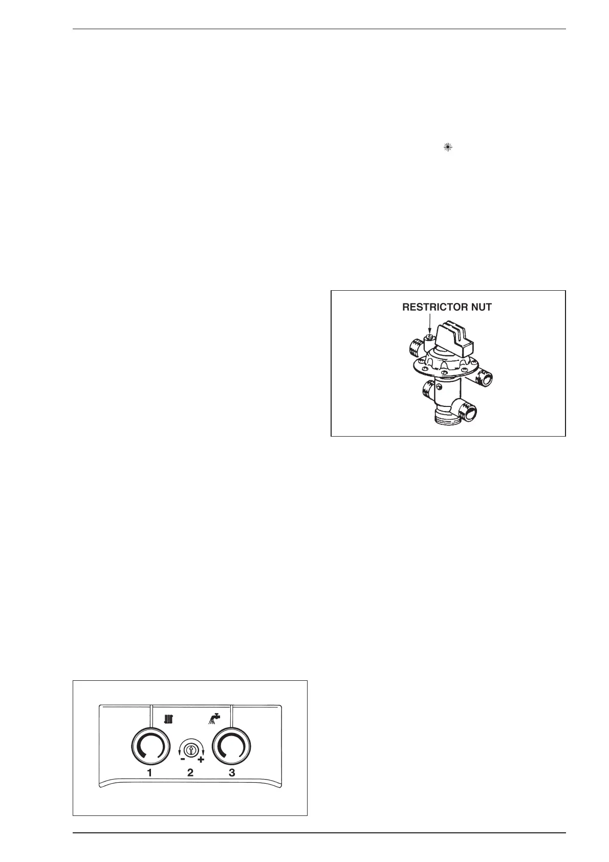
4.4 SETTING THE D.H.W. FLOWRATE
A restrictor screw (fig. 18) is fitted to reduce the D.H.W.
flow to that which will give an acceptable D.H.W. tempera-
ture. To set the D.H.W. flow, procede as follows:
– select Summer position “ ” and turn the D.H.W. ther-
mostat (3 fig. 17) to max. ;
– fully open the D.H.W. tap furthest from the boiler;
–
check that the boiler is firing at maximum burner pressure;
– adjust the D.H.W. flowrate by turning the restrictor
screw on the divertor valve until a D.H.W. temperature
rise of approx 35°C is achieved. This corresponds to the
flowrates shown in table 4;
– turn off the tap;
– remove the pressure gauge and refit the sealing screw;
– relight and test for gas soundness.
4.5 FINAL CHECKS
– Re-fit the casing in reverse order.
– Set the C.H. and D.H.W. potentiometers to the required
settings.
– Ensure that the clock override switch (1 fig. 24) is in the
CLOCK position “¹”, and check that the time clock is
set at the desired time periods. Set the room thermo-
stat (if fitted) to the required setting.
4.6 USER’S INSTRUCTIONS
Upon completion of commissioning and testing the system,
the installer should:
– Give the “Users Instructions” to the householder and
emphasise their responsibilities under the “Gas Safety
(Installation and Use) Regulations 1984”.
– Explain and demonstrate the lighting and shutdown
procedures.
– Advise the householder on the efficient use of the
system, including the use and adjustment of all system
controls for both D.H.W. and C.H.
–
Advise the user of the precautions necessary to prevent
damage to the system, and to the building, in the event of
the system remaining inoperative during frost conditions.
– Explain the function of the boiler overheat thermostat,
and how to reset it. Emphasise that if cut-out persists,
the boiler should be turned off and the installer or servi-
ce engineer consulted.
– Stress the importance of an annual service by a compe-
tent heating engineer.
Fig. 17
Fig. 18