28
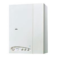
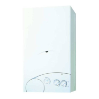
8.12 SPARK GENERATOR FOR “FRIENDLY” MODEL
– Pull off four leads noting their position. If in doubt con-
sult the wiring diagram.
– Remove two screws holding generator to control panel
side wall.
– Replace and reassemble in reverse order.
8.13 IGNITION PCB FOR “FRIENDLY E” MODEL
– Remove the outer casing as described in section 5.1.
– Remove the two screws TCB M4 x 10 (2 fig. 14) and
pivot the control box downwards, then remove the two
self tapping screws (1 fig. 14) and remove the control
box cover.
– Pull off the four connector blocks and the H.T. lead from
the ignition PCB. (The R.H.S. - smaller - PCB), then relea-
se the PCB from it’s mountings.
– Replace the PCB and reassemble in reverse order.
8.14 DRIVER PCB
– Remove the outer casing as described in section 5.1.
– Remove the two screws TCB M4 x 10 (2 fig. 14) and
pivot the control box downwards, then remove the two
self tapping screws (1 fig. 14) and remove the control
box cover.
– Pull off the connector blocks from the driver PCB (The
L.H.S. - larger - PCB for “FRIENDLY E” model).
– Pull off the potentiometer control knobs (1 - 3 fig. 17),
and unscrew the locking nuts.
Release the PCB from it’s mountings by rotating the
mounting pins ⁄turn anticlockwise, and lift it out of the
control box taking care not to lose the potentiometer
spacers.
– Replace the PCB and reassemble in reverse order. Do not
forget to re-fit the spacers.
8.15 PUMP
– Remove the outer casing as described in section 5.1.
– Isolate the C.H. flow and return valves (21 fig. 2), and
drain the appliance through the drain plug situated
below the pump
– Swivel the pump and remove the plastic pump cover (1
screw); disconnect the electrical connections to the
pump.
– Support the pump to prevent it from rotating, and
unscrew both union connections.
– Replace the pump, and reassemble in reverse order,
using the new gaskets supplied with the pump. If the
new pump is fitted with a speed adjuster, ensure that
the speed is set to maximum.
– Refill and commission the system as described in sec-
tion 4.1.
8.16 D.H.W. HEAT EXCHANGER
– Remove the outer casing as described in section 5.1.
– Isolate the C.H. flow and return valves, and the D.H.W.
isolation valve (21 - 20 fig. 2).
– Drain the appliance through the drain plug situated
below the pump and the drain point at the bottom of
the D.H.W. heat exchanger.
– Drain the D.H.W. circuit by opening any D.H.W. tap
below the level of the boiler.
– Remove the two screws TCB M4 x 10 (2 fig. 14) and
pivot the control box downwards.
– Disconnect all union connections to the D.H.W. heat
exchanger and remove the heat exchanger.
– Fit new heat exchanger and reassemble in reverse order
using the new gaskets supplied with the heat exchan-
ger. Refill and re-commission the system as described in
section 4.1.
8.17 DIVERTOR VALVE - COMPLETE
– Remove the outer casing as described in section 5.1.
– Isolate the C.H. flow and return valves, and the D.H.W.
isolation valve (21 - 20 fig. 2).
– Drain the appliance through the drain plug situated
below the pump outlet and the drain point at the bot-
tom of the D.H.W. heat exchanger. Rotate the pump to
the R.H.S. to improve access to the divertor valve.
– Drain the D.H.W. circuit by opening any D.H.W. tap
below the level of the boiler.
– Remove the two screws TCB M4 x 10 (2 fig. 14) and
pivot the control box downwards.
– Disconnect all union connections from the divertor
valve. Withdraw the valve and remove the electrical con-
nections.
– Transfer the electrical connections onto the new valve.
Refer to the wiring diagrams in section 7.
– Re-assemble in reverse order, using the new gaskets
supplied with the valve.
Refill and re-commission the system as described in sec-
tion 4.1.
8.18 DIVERTOR VALVE - MICROSWITCH
ASSEMBLY
– Remove the outer casing as described in section 5.1.
– Rotate the pump to improve access to the divertor valve.
– Pull out the microswitch circlip, (fig. 18) and lift off the
microswitch assembly.
– Transfer the electrical connections onto the new micro-
switch assembly.
Refer to the wiring diagrams in section 7.
– Re-assemble in reverse order.
Temperature (°C) Resistance (Ω)
20 12,000
30 8,300
35 6,900
40 5,800
45 4,900
50 4,100
55 3,500
60 3,000
70 2,200
80 1,700
TABLE 9
 Loading...
