If an electrical fault occurs on the appliance the preliminary
electrical system checks contained in the British Gas
Multimeter Instruction Booklet must be carried out first.
When any service or replacement of electrical components
which has required the breaking and re-making of electrical
connections has taken place, the following tests must be
repeated:
– earth continuity;
– short circuit;
– polarity;
– resistance to earth.
6.1 EARTH CONTINUITY CHECK
Appliances must be electrically disconnected, meter set on Ω
(ohm) x 1 scale and adjust zero if necessary. Tests leads from
any appliance earth point (e.g. inside control box) see wiring
diagrams (section 7) to earth pin on plug. Resistance should
be less than 1 Ω (ohm). If the resistance is greater than 1 Ω
(ohm) check all earth wires for continuity and all contacts are
clean and tight. If the resistance to earth is still greater than
1 Ω (ohm) then this should be reported to your supervisor.
6.2 SHORT CIRCUIT CHECK
Switches turned FULL ON - meter set on Ω (ohms) x 1 scale.
Test leads from L to N on appliance terminal block, if meter
reads 0 then there is a short circuit.
Meter set on Ω (ohm) x 100 scale. Repeat it with leads from
L to E. If meter reads less than infinity (∞) there is a fault.
NOTE: Should it be found that the fuse has failed but
no fault is indicated, a detailed continuity check (i.e.
by disconnecting and checking each component) is
required to trace the faulty component.
It is possible that a fault could occur as a result of local
burning/arcing but no fault could be found under test.
However, a detailed visual inspection should reveal
evidence of burning around the fault.
6.3 POLARITY CHECK
Appliance reconnected to mains supply and meter set on
300 V ac scale. Test at appliance terminal block.
– Test leads from L to N meter reads approx.: 240 V ac.
–
Test leads from L to E “ ” meter reads approx. 240 V ac.
–
Test leads from N to E “ ” meter reads from 0 to 15 V ac.
6.4 RESISTANCE TO EARTH CHECK
Appliance must be disconnected from main supply and
meter on Ω (ohm) x 100 scale.
16
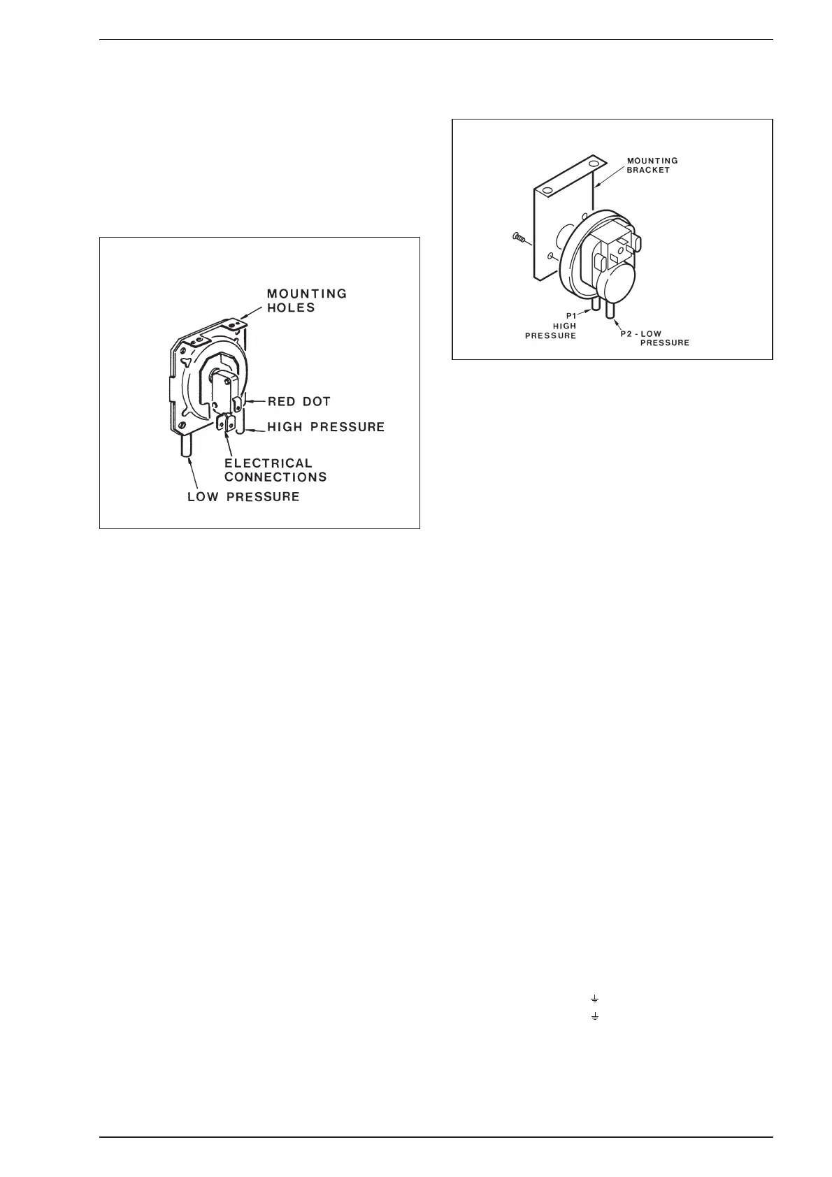
the gas soundness before fitting the outer case.
Ensure that all seals are correctly fitted and that the
pressure sensing lines are correctly fitted as shown in
figs. 21 and 22. Ensure that the earth connection is cor-
rectly refitted. Note that the polarity (Line and Neutral) is
immaterial.
5.6 RE-COMMISSIONING
– Turn on the gas supply, and check for gas soundness
whilst the appliance is running.
– Check the operation of the appliance in both C.H. and
D.H.W. mode and ensure in both cases that the burner
pressure after at least 2 minutes running is as stated on
the data plate or in section 1.3.
Adjust if necessary as described in section 4.
ALTERNATIVE HUBA SWITCH
Fig. 22
Fig. 21
HONEYWELL SWITCH
6 FAULT FINDING