– isolate the mains electricity supply and reconnect
(push on) the two 24 V modulation leads (polarity is
immaterial). Restore the mains supply. The appliance
will light on maximum input. Check that the burner
pressure corresponds to the values given in the pre-
vious points;
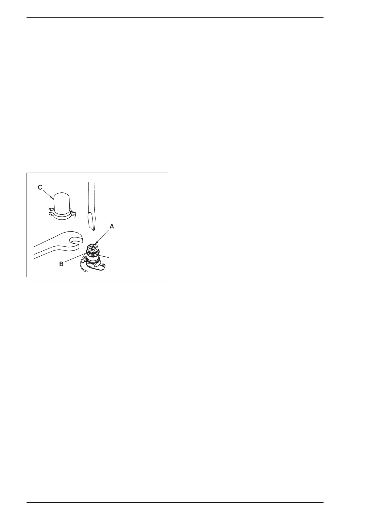
– refit the proportioning unit sealing cap (C fig 28);
– reduce the D.H.W. draw off rate to the minimum
necessary to maintain the burner alight by carefully
adjusting the D.H.W. Inlet valve and check that the
burner pressure decreases in response to D.H.W. tem-
perature rise.Fully open the inlet valve;
– close the D.H.W. tap and ensure that the burner is
extinguished and the pump stops.
– Continue as in section 4.3 to 4.5.
8.7 PRESSURE SWITCH
Two types of pressure switch are available on this
appliance, HONEYWELL or HUBA. Both are fully inter-
changeable, and figs. 21 - 22 shows the differences
between them. Note that the HUBA switch has a
bracket not required by the HONEYWELL switch.
– Remove the outer casing and the sealed chamber front
panel as described in section 5.1.
– Disconnect the pressure sensing pipes from the switch
(fig. 20).
– Disconnect the electrical connections from the switch.
– Unscrew and remove the two screws securing the moun-
ting bracket (HUBA) or switch body (HONEYWELL).
– (HUBA only) Remove the switch from the bracket (two
screws) and fit the new one.
– Fit the new switch and re-assemble in reverse order
referring to figs. 21 - 22 and the wiring diagrams (sec-
tion 7) as appropriate.
8.8 LIMIT THERMOSTAT
The limit thermostat is situated on the top, L.H.S. of the
heat exchanger (19 fig. 24).
– Remove the outer casing and the sealed chamber front
panel as described in section 5.1.
– Without disconnecting the wires, unscrew the two limit
thermostat fixing screws.
– Lift the thermostat and fixing screws out using the wires.
– Replace the thermostat and spread heat sink compound
(supplied) over the base of the new one.
Connect the wires, (polarity is immaterial) and position
the screws in the flange and re-fit using the wires to
position the thermostat before tightening the screws.
– Re-assemble in reverse order.
8.9 THERMOCOUPLE AND OVERHEAT
THERMOSTAT FOR “FRIENDLY” MODEL
– Remove the combustion chamber front panel as descri-
bed in section 5.1.
– Loosen thermocouple retaining nut at pilot burner and
pull out thermocouple.
Work thermocouple through plastic grommet at the
base of combustion chamber.
– Remove the two screws retaining overheat thermostat
(10 fig. 24).
– Unscrew thermocouple from rear of gas valve.
– Replace and reassemble in reverse order.
8.10 OVERHEAT THERMOSTAT
FOR “FRIENDLY E” MODEL
The bulb of the overheat thermostat (10 fig. 24) is positioned
in a phial pocket alongside the air separator in the flow pipe.
– Remove the outer casing as described in section 5.1.
– From below the boiler, unscrew and remove the
overheat thermostat locking nut to release the thermo-
stat body.
– Remove the two screws TCB M4 x 10 (2 fig.14) and
pivot the control box downwards, then remove the two
self tapping screws (1 fig. 14) and remove the control
box cover.
– Withdraw the thermostat then pull off the two electrical
connections
– Remove the lower “key ring” securing the thermostat
phial in its pocket and remove the phial by sliding it
downwards. Withdraw the phial through the grommet
in the control box.
– Re-assemble in reverse order ensuring that the new
phial is coated in heat sink compound (supplied) and
correctly positioned and secured in it’s pocket. Note that
the electrical polarity is immaterial.
8.11 THERMISTOR - C.H. OR D.H.W.
The thermistors are screwed in fittings on the flow pipe
(C.H.) and D.H.W. outlet pipe (D.H.W.).
The thermistors do not penetrate the waterways, therefore
it is not necessary to drain the appliance (fig. 24).
– Remove the outer casing as described in section 5.1.
– Pull off both electrical connections from the faulty ther-
mistor, unscrew the thermistor, replace and re-assemble
in reverse order using the heat sink compound supplied.
Note that the polarity of the thermistor connections is
immaterial.
The sensors are NTC mod. ST03 ones and are inter-
changeable.
Table 9 shows the resistance values that are obtained on the
sensors as the temperature varies.
27
KEY
A Plastic screw
B Nut
C Sealing cap
Fig. 28