3.5 FLUE AND TERMINAL INSTALLATION
3.5.1 Installations from inside the room
Wall thicknesses up to 0.5 m (19 in) only, Hole diameter suf-
ficient to accept wall liner. 130 mm (5
1
/
4
in) if optional kit is
used fig. 13.
– A wall liner, 127 mm (5 in) internal diameter, 500 mm
(19 in) long is available as an optional extra for use
when fitting the flue/air duct from inside the building,
(or where it is required to seal the hole through a cavity
wall). Cut the liner to the wall thickness, insert into the
hole, and seal with mortar at inner and outer wall faces.
Access to the outside can be made by inserting one’s
hand through the liner.
– Fit the rubber sealing ring into the swaged groove in the
air duct as shown in fig. 13. Ensure that it is the correct
way around and spray the outside surface with talcum
powder or soap solution to reduce friction.
– Push the flue duct assembly into the air duct until the
external swaged ring on the flue terminal stops against
the internal swage on the air duct (fig. 12).
– From inside the building slide the duct assembly into the
wall liner until the sealing ring passes completely throu-
gh the wall, then pull the air duct back until the ring is
pulled up to the wall surface.
– Procede to section 3.5.3.
3.5.2 Installations from outside the building only
(Hole diameter 100 mm - 4in)
– Push the flue duct assembly into the air duct until the
external swaged ring on the flue terminal stops against
the internal swage on the air duct (fig. 12).
– From inside or outside the building, slide the duct
assembly into the wall until the sealing ring forms a
good seal against the outside wall.
– Fit the rubber sealing ring into the swaged groove in the
air duct as shown in fig. 13. Ensure that it is the correct
way around.
3.5.3 Connecting the duct assembly
All installations
– With reference to fig. 13, slide on the aluminium reten-
tion ring (D), check that the rubber sealing ring (E) is
pulled up to the wall and that the duct assembly is hori-
zontal, then secure the aluminium retention ring to the
air duct using the two screws (H) provided. Do not over-
tighten the screws.
– Push the junction collar (B) over the air duct until the air
duct touches the inner part of the collar where the dia-
meter becomes smaller.
– Push the elbow socket into the junction collar and onto
the flue duct.
– Fit the protective metal collar (I) over the juction collar.
– Release the two spring clips and remove the four fixing
screws securing the sealed chamber front panel then
remove the panel.
– Place the gasket (G) under the flange of the elbow and fit
the elbow onto the top of the appliance, taking care to
ensure that the silicon seal on the fan outlet correctly
engages and forms a seal at its joint with the elbow. This
must be checked from inside the sealed chamber.
– Secure the elbow onto the top of the appliance using
the four screws and washers provided, and refit the sea-
led chamber front panel.
3.6 WATER CONNECTIONS
3.6.1 Central heating connections
–
Fit the two C.H. isolation valves using the gaskets
supplied to the flow and return connections as shown
in fig. 2.
The pipe connections are labelled on the lower part of
the boiler.
– Connect the C.H. pipework as required.
3.6.2 D.H.W. connections
– Fit the D.H.W. isolation valve to the cold water inlet con-
nection as shown in fig. 2.
– Fit the union connection to the D.H.W. outlet.
– Connect the D.H.W. pipework as required.
– If a D.H.W. expansion vessel is to be fitted, remove the
screwed plug from the D.H.W. expansion vessel connec-
tion on the left of the appliance, and screw the vessel
into position using a jointing compound suitable for
potable water.
11
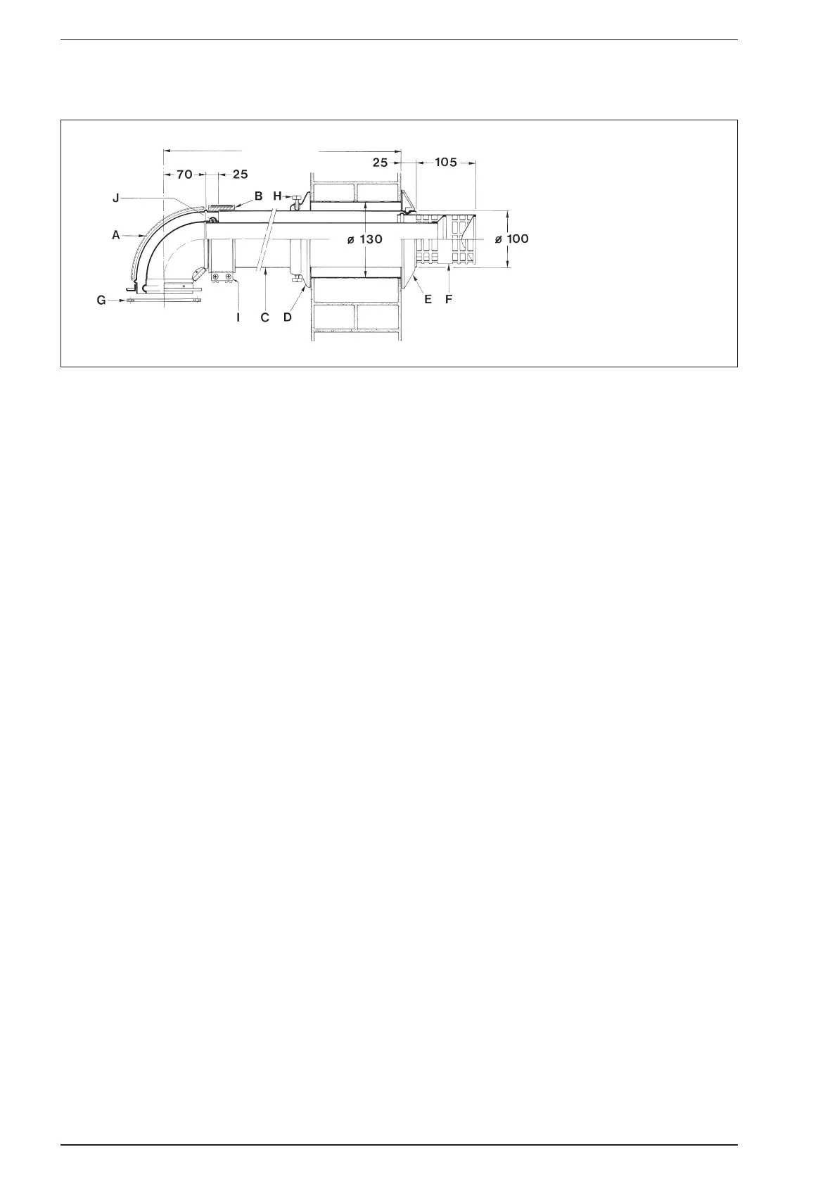
KEY
A Elbow flange
B Junction collar
C Outer duct
D Aluminium ring
E Rubber sealing ring
F Inner duct c/w terminal
G Gasket ø 95/125 x 2
H Fixing screw
I Protective metal collar
J Inner “O” ring
Z
Fig. 13