Before commencing any service operation, ISOLATE the
mains electrical supply, and TURN OFF the gas supply at the
main service cock.
It is the law that any service work must be carried out by a
competent person such as British gas or other Corgi regi-
stered personnel.
8.1 HEAT EXCHANGER
– Remove the fan as described in section 8.3.
– Remove the anti-vibration spring on the top of the col-
lector hood (fig. 20).
– Lift the collector hood assembly, tilt forwards, and remo-
ve the hood.
– Isolate the C.H. flow and return valves.
– Drain the heat exchanger using the drain cock (fig. 2).
– Unscrew the two heat exchanger unions and the locking
nuts, then lift out the heat exchanger.
– Re-assemble in reverse order, ensuring that the pressure
sensing pipes and anti vibration spring are correctly re-
fitted (figs. 20 - 21 - 22). The fan polarity is not impor-
tant except the earth conductor (G/Y which is marked
on the appliance). Refill, and re-commission the system
as described in section 4.
8.2 COMBUSTION CHAMBER INSULATION
The design of this appliance is such that the rear and side
insulation should not require replacement unless mechani-
cally damaged. To replace the insulation front panel, pro-
ceed as follows:
– remove the combustion chamber front panel as descri-
bed in section 5.1;
– replace the front insulation panel and glue it into posi-
tion on the front panel using the glue supplied. Re-
assemble in reverse order.
Should the rear or side panels become damaged, replace
them as follows.
– remove the heat exchanger as described in section 8.1;
–
remove the side insulation panels followed by the rear panel;
– re-assemble in reverse order, refill, and recommission the
system as described in section 4.
8.3 FAN ASSEMBLY
– Remove the outer casing and the sealed chamber front
panel as described in section 5.1.
– Disconnect the electrical connections to the fan. Note
the position of the earth conductor.
– Pull off the two pressure sensing lines (fig. 20).
– Unscrew the four screws securing the fan mounting
plate.
– Drop and tilt the fan assembly forwards and remove in a
downwards direction.
– Unscrew the three screws retaining the fan on the fan
plate (14 fig. 24). Remove the fan assembly.
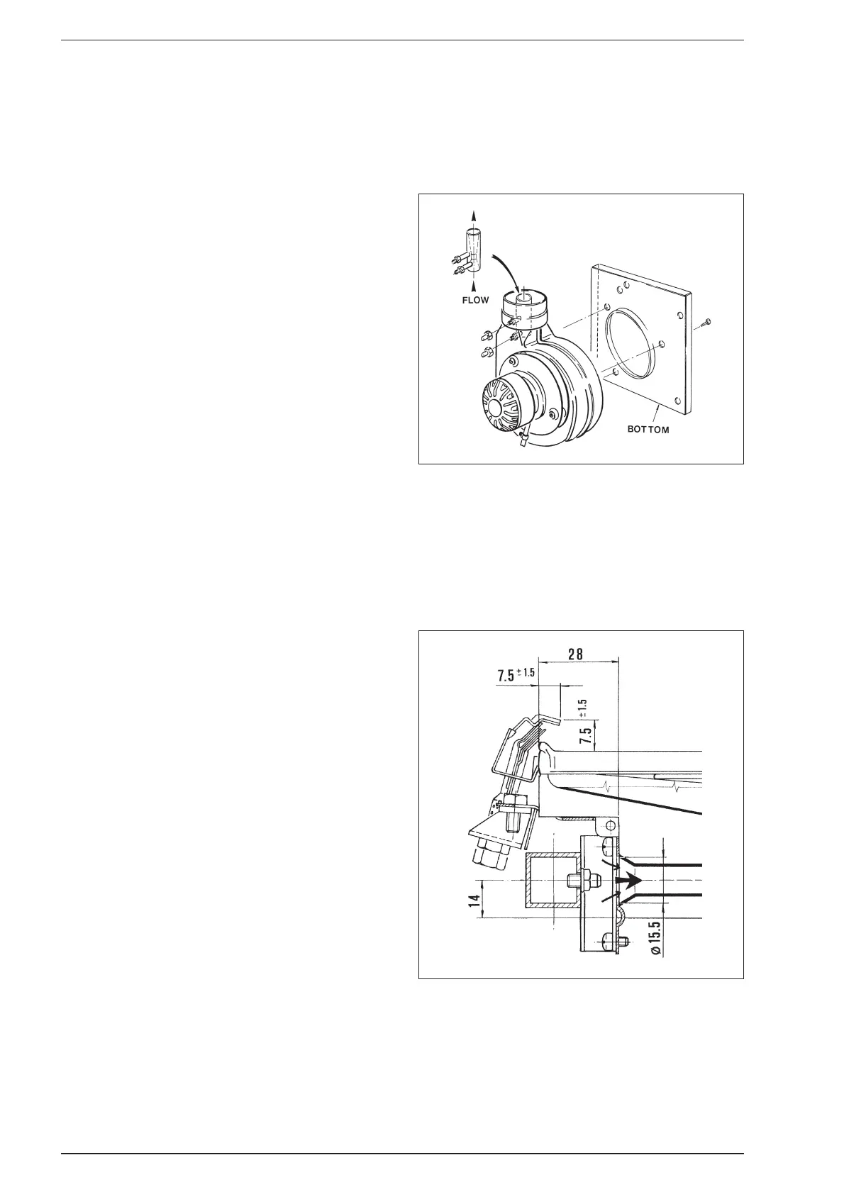
– Transfer the pressure sensing Venturi from the old fan to
the new one, ensuring that it is fitted in the correct
direction as shown in fig. 25.
– Transfer the fan outlet seal onto the new fan.
– Reassemble in reverse order. Ensure that the earth con-
nection is correctly refitted. Note that the polarity (Line
and Neutral) is immaterial. Ensure that the pressure sen-
sing leads are correctly connected - red dot to red dot
and plain to plain.
8.4 MAIN BURNER
– Remove the main burner by following section 5.1.
–
Transfer the pilot assembly onto the new burner assembly.
–
Re-assemble in reverse order and check for gas soundness.
8.5 PILOT BURNER ASSEMBLY AND ELECTRODE
“FRIENDLY” model
– Remove the combustion chamber front panel as descri-
bed in section 5.1.
– Unscrew the pilot pipe from the pilot burner and with-
draw. Carefully remove the pilot injector.
– Unscrew the thermocouple and spark electrode connec-
tions and remove from pilot bracket. Unscrew the two
screws holding the pilot bracket and lift clear.
25
8 REPLACEMENT OF PARTS
Fig. 25
Fig. 26