22
7 INTERNAL WIRING DIAGRAMS AND VIEWS
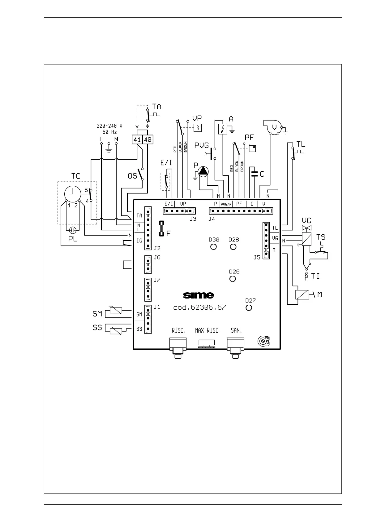
7.1 FUNCTIONAL FLOW WIRING DIAGRAM “FRIENDLY” MODEL
Fig. 23/a
KEY
L Phase
N Neutral
SS D.H.W. temperature sensor (red)
SM Outlet C.H. temperature sensor (blue)
TC Time clock
PL Power-on lamp
OS Time clock overriding switch
F Fuse (T 1.6 A)
TA Room stat
E/I Summer/Winter switch
VP Diverter valve
P Circulating pump
PVG Gas control push-button
A Delayed ignition
PF Smoke pressure switch
C Fan capacitor
V Fan
TL Limit stat 85°C
VG Gas valve
TS H.L. stat 100°C
TI Interrupted thermocouple
M Modulating coil
D30 Smoke pressure switch led
D28 Line led
D26 Interrupted C.H. thermistor
D27 Ignition led