3
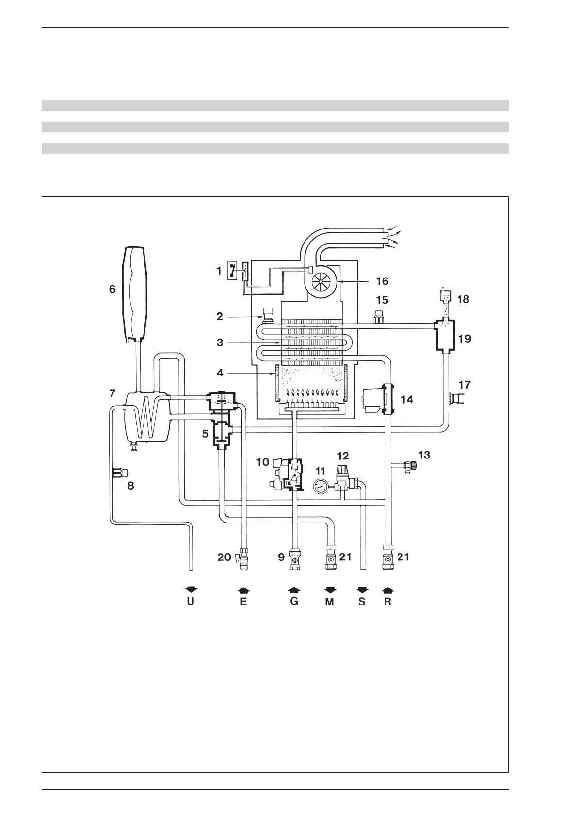
1.4 HYDRAULIC CIRCUIT
KEY
1 Air pressure switch
2 Limit thermostat
3 Heat exchanger
4 Combustion chamber
5 Divertor valve
6 C.H. expansion vessel
7 D.H.W. heat exchanger (calorifier)
8 D.H.W. thermistor
9 Gas cock
10 Multifunctional gas control
11 Pressure gauge
12 Safety valve
13 Drain cock
14 Circulating pump
15 C.H. thermistor
16 Fan
17 Safety thermostat (“FRIENDLY” model)
18 Automatic air vent
19 Air separator
20 D.H.W. isolation valve
21 C.H. isolation valves
TABLE 5 - Maximum flue lengths
Rear outlet L.H. side outlet R.H. side outlet
mm in mm in mm in
STANDARD FLUE KIT 745 29
1
⁄4 690 27
1
⁄4 630 24
3
⁄4
WITH ONE EXTENSION KIT 1,560 61
1
⁄2 1,505 59
1
⁄4 1,445 56
3
⁄4
WITH TWO EXTENSION KITS 2,375 93
1
⁄2 2,320 91
1
⁄4 2,260 89
Fig. 2