13
Before commissioning the appliance, the whole gas installa-
tion including the meter MUST be purged and tested for gas
soundness in accordance with BS6891: 1988.
IMPORTANT: open all doors and windows, extinguish
naked lights, and DO NOT SMOKE whilst purging the
gas line.
Before commencing the commissioning procedure,
ensure that the gas service cock is turned on, the elec-
tricity supply is isolated, and that the D.H.W. and C.H.
isolation valves are in the closed position.
4.1 FILLING THE WATER SYSTEM
– Open the C.H. flow and C.H. return valves (21 fig. 2).
– Loosen the automatic air vent cap (18 fig. 2) on the flow
pipe near the heat exchanger.
– Open all radiator valves and system air vents.
Fill the system with water using one of the approved
methods described in section 2.9 to about 0.5 bar grea-
ter than the system design pressure. Close all air vents.
Do not forget the one near the pump!
– Check the system for water soundness.
– Completely drain the appliance and heating system,
thoroughly flush the system, and refill the system design
pressure.
– Open the D.H.W. inlet valve, open any hot tap, clear of
air bubbles. Close hot tap.
4.2 COMMISSIONING THE BOILER
4.2.1 V4600C mounted on “FRIENDLY” model
– Remove the screw and connect a pressure gauge to the
burner pressure test point on the gas valve (5 fig. 16/a).
– Set the Summer/Winter switch (2 fig. 24/a) to SUMMER.
Check the gas service cock is ON. Ensure that the time
clock is ON and the room thermostat is calling for heat.
Switch on the electrical supply to the boiler. Fully
depress the gas valve control button and hold in. After
approximately 15 secs. a spark will light the pilot (check
through viewing window). After a further 20 secs. relea-
se the button and the pilot should remain alight.
NOTE: on initial lighting it may take some time to
purge the air from the pilot pipe.
Check the pilot flame fully envelops 5 - 8 mm of the
thermocouple tip. If necessary adjust using regulating
screw on gas valve (6 fig. 16/a). Turn the D.H.W. tempe-
rature adjuster fully clockwise to maximum (3 fig. 17).
Fully open any D.H.W. tap and the burner will light.
–
Allow the boiler to run for at least 2 minutes and check
that the burner pressure is as stated in section 1.3. The
D.H.W. burner pressure is factory set and should not
require adjusting. If the burner pressure is low, check that
the appliance has not begun to modulate (this will occur
if the D.H.W. flow rate is low. If modulation is suspected,
open all D.H.W. taps to maximise flow and recheck bur-
ner pressure). If it is necessary to adjust the D.H.W. bur-
ner pressure the method is described in section 8.6.
– Reduce the D.H.W. draw off rate to the minimum neces-
sary to maintain the burner alight by carefully adjusting
the D.H.W. inlet valve and check that the burner pressu-
re decreases in response to D.H.W. temperature rise.
Fully open the inlet valve.
– Close the D.H.W. tap and ensure that the burner is
extinguished and the pump stops.
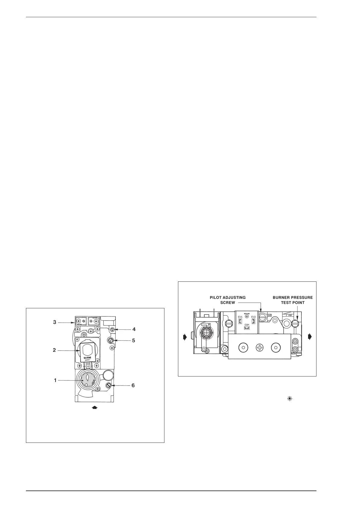
4.2.2 SIT 837 TANDEM mounted on “FRIENDLY E” model
– Remove the screw and connect a pressure gauge to the
burner pressure test point on the gas valve (fig. 16/b).
–
Ensure that the Summer/Winter switch on the facia panel
(2 fig. 24/b) is set to the SUMMER position “ ” (D.H.W.
Only), turn the D.H.W. thermostat (3 fig. 17) to maximum
(fully clockwise), and turn on the electrical supply. Fully
open any D.H.W. tap and the burner will light.
–
Allow the boiler to run for at least 2 minutes and check
that the burner pressure is as stated in section 1.3.
The D.H.W. burner pressure is factory set and should not
require adjusting. If the burner pressure is low, check that
the appliance has not begun to modulate (this will occur
if the D.H.W. flow rate is low. If modulation is suspected,
open all D.H.W. taps to maximise flow and recheck bur-
ner pressure). If it is necessary to adjust the D.H.W. bur-
ner pressure the method is described in section 8.6.
4 COMMISSIONING AND TESTING
KEY
1 Control button
2 Modulating coil
3 Electric operator
Fig. 16/a
Fig. 16/b
4 Inlet pressure test point
5 Burner pressure test point
6 Pilot adjusting screw