User Manual For - CONTROLLER/DATA RECORDER MultiCon CMC-99/141
7.8.11.4. Application of Logical channel in the Hardware output monitor mode for R45
modules
See also:
Appendices
8.13. R45, R81, R65, R121 - RELAY MODULES.
Task:
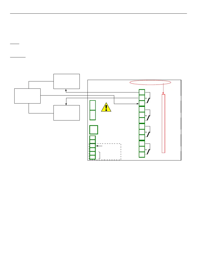
This example shows how to read the value from the output module
R45
.
Solution:
Before connecting a relay to the device, the user should configure the device, and then
connect them as it is shown in
Fig. 7.73
. After setting the configuration of the physical inputs
we can configure the input channel to read the output value.
Fig. 7.73. Schematic diagram for the R45 module
134
Power supply
(depending on version)
1
2
8
5
6
7
3
4
SERVICE
+24V DC ±5%
(
I
max. = 200mA)
digital input
0/15..24V DC
RS-485
GND
GND
A+
B-
isolated
R45
4 relay 5A/250V
n01
n02
n03
n04
n05
n06
n07
n08
n09
n10
n11
n12
OUT1
OUT2
OUT3
OUT4
Lower
actuator
Upper
actuator
Supply
220V
GND
Slot C
Out.C1 : Relay
Out.C2 : Relay
Out.C3 : Relay
Out.C4 : Relay
GND

 Loading...