User Manual For - CONTROLLER/DATA RECORDER MultiCon CMC-99/141
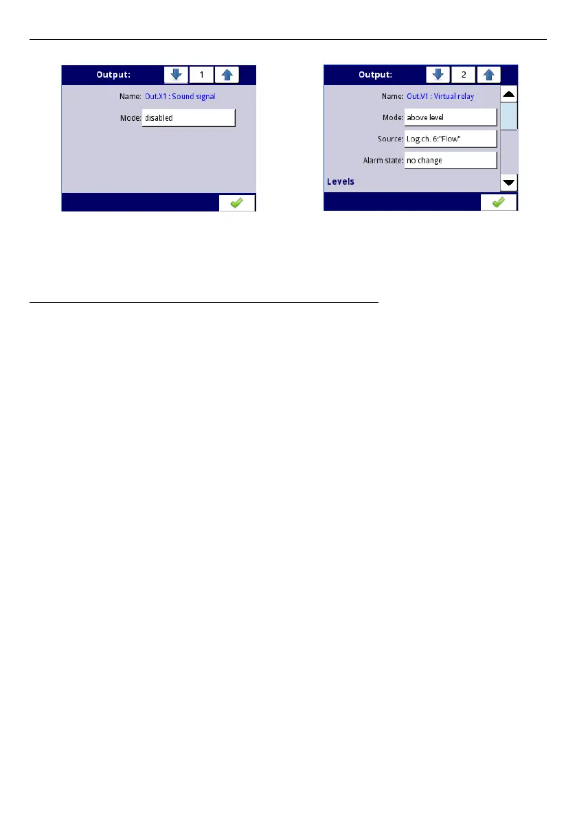
Fig. 7.86. Main settings of disabled (left) and enabled (right) output
State of physical outputs can be used as a source for
Logical Channels
(for details see
Chapter 7.8.3. Logical Channels - Hardware output monitor mode
)
7.10.2. Built-in Output - Relays, Sound signal, Virtual relays
The parameters of
Built-in outputs
for: Relays, Sound signal, Virtual relays are:
–
Name
- each output already has a name given by the device and the user cannot
change it, for the description of the
Name
parameter see
Fig.
7.84
,
–
Mode
- this parameter allows the user to select the method of operation of the
output, the
Mode
parameter has the following options (see
Fig.
7.87
and
Fig.
7.88
):
•
disabled
- the built-in output is inactive,
•
above level
- the result is a high state when the input data (see the the
Source
parameter) is above the level (see the
Level
parameter block), otherwise the
output is low state,
•
below level
- the result is a high state when the input data (see the
Source
parameter) is below the level (see the
Level
parameter block), otherwise the
output is low state,
•
inside range
- the result is a high state when the input data (see the
Source
parameter) will be within the range (see the
Level
parameter block), otherwise
the output is low state,
•
outside range
- the result is a high state when the input data (see the
Source
parameter) will be out of the range (see the
Level
parameter block), otherwise
the output is low state,
•
PWM
- this option is visible only for the SSR relay output type, the PWM mode is
discussed in
Chapter 7.10.3. Built-in output - PWM (Pulse-width modulation)
mode for SSR relay output
,
–
Source
- this parameter contains a list of logical channels (up to 60), where the
selected logical channel will be a data source for this built-in output (see
Fig.
7.85
).
–
Alarm state
– this parameter allows to choose a type of output reaction in case of
the alarm state appearance; The
Alarm state
is when the value of a Logical channel
in which the data source for a built-in output returns
-Err-
state or the state of the
exceeding range: low
-Lo-
state and high
-Hi-
state; There are the following options
in this parameter:
•
no change
- means that at the time of an alarm state there is no change in the
output,
•
immediate OFF
- means that in times of an alarm state the device immediately
switches the output to low state,
165

 Loading...