User Manual For - CONTROLLER/DATA RECORDER MultiCon CMC-99/141
FI2 FI4 FT2 FT4
Input signals voltage
levels:
logical LOW state
logical HIGH state
-
-
-
-
| Uin | < 1V
| Uin | ≥ 10V
| Uin | < 1V
| Uin | ≥ 10V
Max input voltage 5V 5V 30V 30V
Sampling period 50ms 50ms 50ms 50ms
Max. input frequency - - 50kHz 50kHz
Totalizer capacity 1 000 000 000 000 1 000 000 000 000 1 000 000 000 000 1 000 000 000 000
Isolation strength 1 min. @ 500V AC 1 min. @ 500V AC 1 min. @ 500V AC 1 min. @ 500V AC
Weight 48 g 58 g 52 g 72 g
*
Measurement ranges are limited by software upon hardware inputs ability, check the current list of
MultiCon CMC-99/141
measurement ranges at the producer's website
Tab. 8.6 Technical data for the module FI2, FI4, FT2, FT4
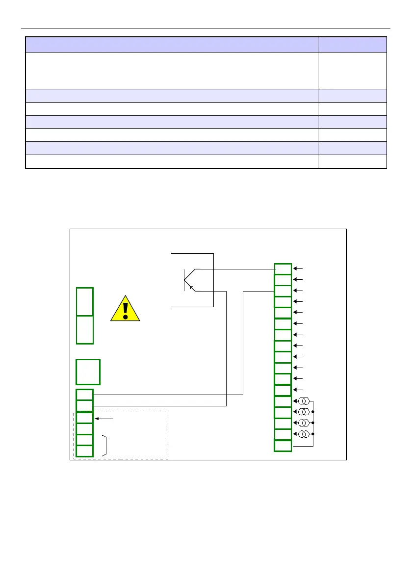
Fig. 8.11. FT4 module and PNP type sensor connection scheme
277
PNP
Power supply
(depending on version)
1
2
8
5
6
7
3
4
SERVICE
+24V DC ±5% (Imax. = 200mA)
digital input
0/15..24V DC
RS-485
GND
GND
A+
B-
isolated
FT4
4 pulse inputs
+ 4 current inputs
n15
n16
n17
n04
n05
n13
n14
n01
n02
n03
n04
n05
n01
n02
n03
n06
n10
n11
n07
n08
n09
n12
GND
IN5
IN6
IN7
IN8
4 x 0-20mA
COM4
Inp42
Inp41
COM3
Inp32
Inp31
COM2
Inp22
Inp21
COM1
Inp12
Inp11

 Loading...