24
6. Remove the retainer from the back box.
7. Remove the knockout plugs on the back box for wire entry.
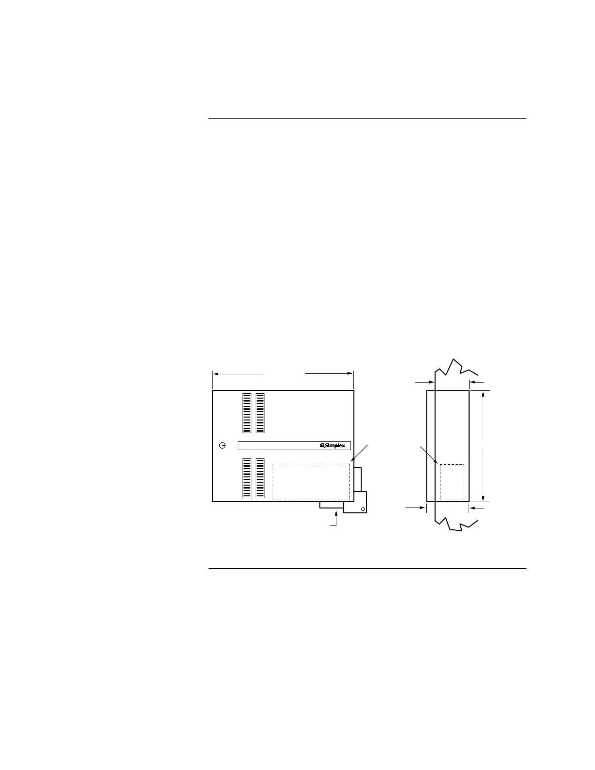
8. At the 4003 mounting location, install the 4003 back box as shown in
Figure 12.
a. Position the back box on two wall-mounted screws capable of
supporting the panel with batteries using the special keyholes at the top
of the box.
b. Tighten screws until snug.
c. Insert a mounting screw in each of the two mounting holes at the
bottom of the box and tighten these screws until snug.
Note: For semi-flush mounting, the back box must be extended 1 1/2 inches
from the finished wall. Refer to the "Rough Opening" section of the
Back Box Installation Chart (Figure 12).
4003 VOICE CONTROL
DOOR WIDTH
26 "
660mm
BOX WIDTH
25 3/4'
BEIGE SEMI-FLUSH TRIM
2975-9801
"
WALL
SURFACE
BATTERY
MOUNTING AREA:
AVOID BOTTOM
ENTRY CONDUIT IN
THIS SPACE
4"
101mm
20 3/4'
4 1/4'
Figure 12. Installing the 4003 Back Box
Mounting the 4003, Continued
Mounting Procedure
(continued)