25
Refer to the 841-921 Field Wiring Diagram, the Wiring Information mounted on
the inside of the 4003 panel door, the 4003 Voice Control Panel Connection
Diagram (Figure 13), and the system wiring requirements listed below when
wiring the 4003.
• All wires are to be copper conductors only.
• All wiring, except incoming power and ground connecting wires, must be
free from grounds or shorts and have a resistance of one megohm, or higher,
to EARTH.
• All wiring shall be terminated with UL listed devices (i.e., wire nuts,
pressure connectors, etc.). Wiring terminated with only electrical tape is not
permitted. All splicing (free ends of conductors) shall be covered with an
insulation equivalent to that of the conductors.
• When running wires to the 4003, identify the wires appropriately: Input
power, dedicated IDC wiring (if not connected to a 4020 FACP), dedicated
NAC wiring, RUI wiring (if required), Remote Microphone wiring (if
required), external battery connection (if required), and the four NAC
circuits (an additional four NAC circuits are available as a field-installed
option).
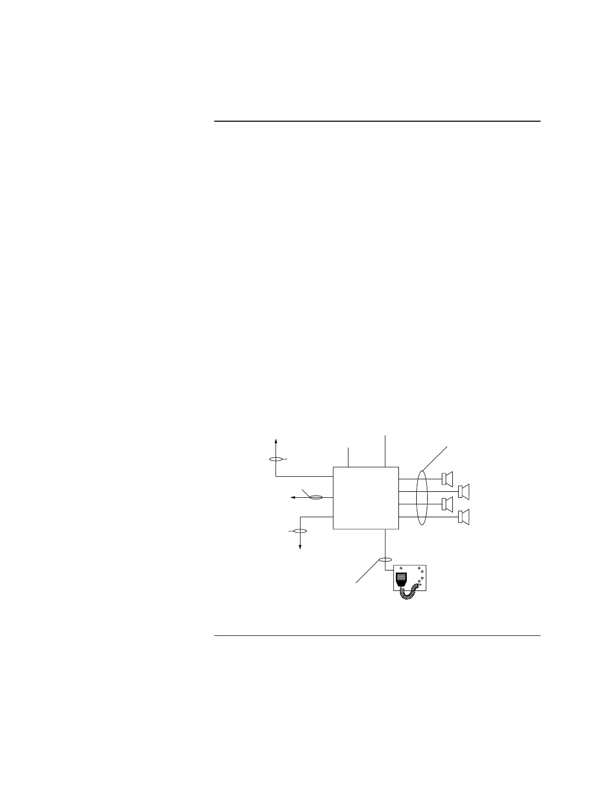
4003 VOICE
CONTROL PANEL
NOTIFICATION APPLIANCE CIRCUITS,
FOUR STYLE Y STANDARD (STYLE Z OPTIONAL)
RATED 2A @ 25VRMS
(ADDITIONAL FOUR CIRCUITS AVAILABLE
FIELD INSTALLED ONLY)
EXTERNAL
BATTERY
CONNECTION
(IF REQUIRED)
AC INPUT
POWER
2, #13 AWG MIN
TO RUI COMMUNICATIONS (WHEN
CONNECTED TO A SIMPLEX 4020
FIRE CONTROL PANEL)
4003-9803 SUPERVISED REMOTE
MICROPHONE WITH KEYSWITCH
AND READY TO TALK LED
MOUNTS ON 2 GANG BOX.
1 PAIR #18 AWG TWISTED, SHEILDED CABLE,
PLUS 5 #18 AWG CONTROL WIRES.
MAXIMUM DISTANCE 4500 FT. (762M).
2, #14 AWG MIN
#18 TWISTED,
SHEILDED PAIR
TO DEDICATED NOTIFICATION
APPLIANCE CIRCUIT OF HOST
FIRE ALARM CONTROL PANEL
TO DEDICATED IDC OF
HOST FIRE ALARM CONTROL
PANEL (NOT REQUIRED IF
CONNECTED TO 4020)
Figure 13. 4003 VCP Connection Diagram
Wiring the 4003
Wiring Requirements