4020 OPERATORS MANUAL Page 11
Document No: 4020-M010 1st February, 1997 Issue 2.0
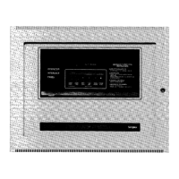
5.1 OPERATOR FRONT PANEL
Figure 1.2 shows the layout of the front panel operator controls. These are described as
follows:
The Panel buzzer will sound under alarm and fault conditions until silenced during the
response procedure.
The Audible Positive Feedback Device sounds when any key on the panel is pressed
as an indication that the keystroke has been registered.
The Alarm light will illuminate when there is an alarm in any one of the zones protected
by the system.
The Fault light will illuminate when there is a fault in the system at any stage.
The Isolated light will only illuminate when the Isolate button is pressed to isolate zones.
When any zone is isolated, it will not send any alarm to the master alarm facility and
the isolated light will illuminate.
The Bell Isolated light will illuminate when the panel door is opened. This isolates the
building alarm bell.
The Power On light indicates that the 240 V supply is available. If the 240 V supply
fails, the system switches to battery supply, the Power On light turns off and the fault
light illuminates.
The Isolated ACF light (Ancillary Control Facility). The Isolated ACF light will only
illuminate if the panel door is opened and there is no alarm present on the panel. The
building ancillaries include the air conditioning shut downs, magnetic fire door holders,
alarm buzzers, lights, and other outputs. The light indicates that all the ancillary circuits
programmed to be isolated via the door switch are isolated when the panel door is
opened and there are no alarms present on the panel.
The Text Window consists of two lines of text which describe the status of the system in
four modes.
Normal mode is the normal operational state of the panel. It shows:
SIMPLEX AUSTRALIA - Time of day - Bat: OK
Alarms: 0 Faults: 00 Isolated : 00

 Loading...


