Page 42
Document No: 4020-M010 1st February, 1997 Issue 2.0
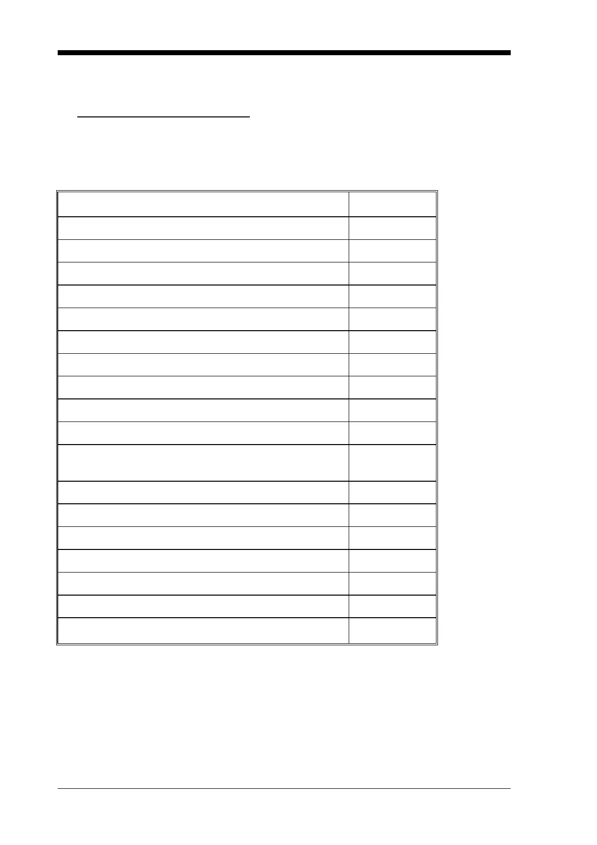
9.2 COMMISSIONING CHECKLIST
Check each item to ensure that system has been installed correctly and is functioning
normally.
ITEM
CHECKED
Panel configuration as per specification
Cabinet undamaged and paintwork clean
Window undamaged and fitted correctly
Manual Call Point fitted and wired to alarm zone 1
Cabinet sealed to dust level.
Membrane keyboard fitted and aligned correctly
LCD display fitted and aligned correctly
LED indicators fitted and aligned correctly
Keylock type 003 fitted
"Mains Isolation" switch is labelled
Mains terminations correct and earth terminations
secure
Internal wiring correct and neatly loomed
Bell fuse F4 fitted and rated at 1A
External 24V DC fuse F5 fitted and rated at 2A
Panel ratings label completed and affixed to panel
Battery terminals insulated
System wired to "as installed drawings"
Log book installed in cabinet