2-5
Note: Unless otherwise noted, wiring is not supervised.
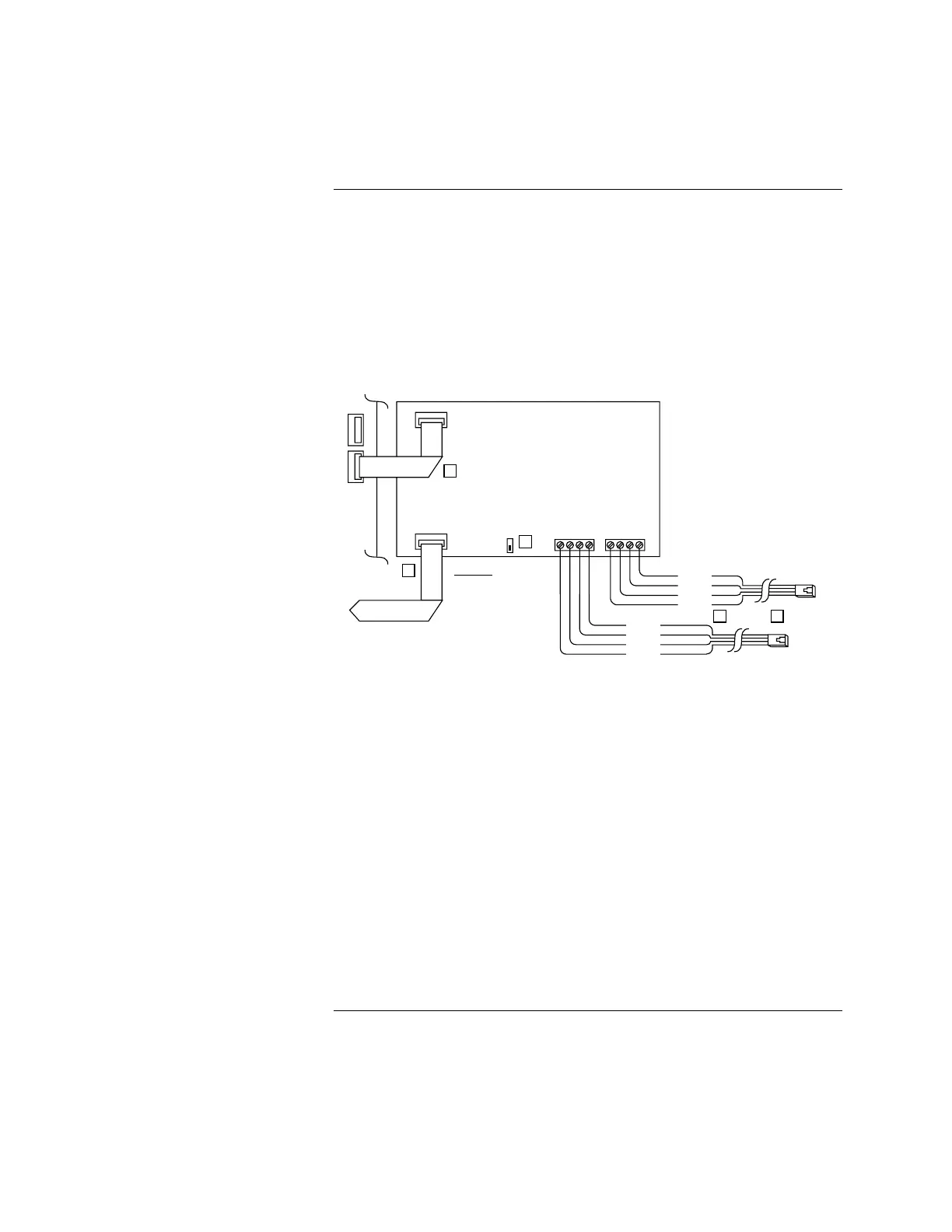
1. Wire the 4004-9810 CCDACT into the system in accordance with Figure
2-2 and the references below the figure.
2. Route the TELCO cables using separate paths from the panel exit to the
RJ-31X modules.
3. Use the cable tie-wrap (supplied) to provide strain relief for these cables.
Secure the cables to the standoff / tie-wrap mount described in Step 7
(previous page).
Contact Closure DACT
565-626
TB3 TB4
4004 CPU
Board
P5
1
P1
P2
1
11
To Programmer
1
4
5
32 To RJ-31 Jack
(BLU)
(RED)
(GRY)
(GRN)
(BLU)
(RED)
(GRY)
(GRN)
HOUSE-R1
RING 1
HOUSE-T1
TIP 1
HOUSE-R2
RING 2
HOUSE-T2
TIP 2
2 TxD Out
9 Common
10 RxD In
RS232
Figure 2-2. Wiring the 4004-9810 CCDACT into the System
Figure References:
1. Connect CCDACT (P2) to 4004 system board (P5 on 565-573) using the
733-885 harness. Match the odd-colored harness wire with the PC board
Pin 1 designator at each end.
2. Power-limited wiring; route TELCO cables up side of panel to top right-hand
panel exit. Using harness STR P/N 2080-9046 (7 ft cable), -9047 (14 ft cable), or
equivalent, connect to TELCO jacks. Splice as required using 22 AWG wire
(minimum) to complete desired span. TELCO wiring is supervised.
3. Use the cable tie-wrap (supplied) to provide strain relief for these cables. Run the
TELCO cable jacket through the tie-wrap loop.
Make the terminal block-to-
spade lug connections for both TELCO cables; then tighten the tie-wrap down
around the cable jackets and the mounting stand-off.
4. Cable connection to programmer is only present during setup.
5. CCDACT Self-Test Switch: Slide to "ON" position for self-test. Return
to "OFF" position for normal operation.
Continued on next page
Installing the 4004-9810 CCDACT Kit, Continued
Wiring the 4004-9810 CCDACT
into the System