6 - 31
6 General Repair
6B Hand Controls Repair
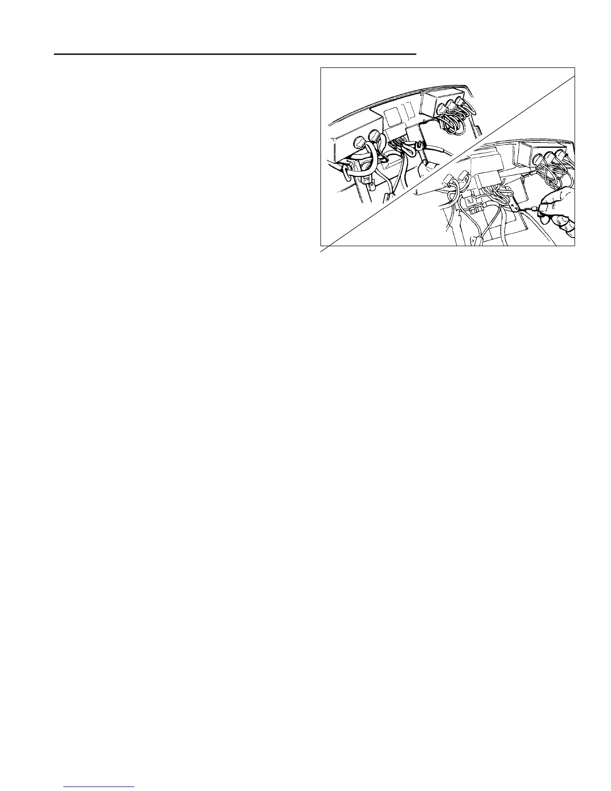
Figure B–34. Remove Wire Clip & Throttle Cable
From Throttle Lever
Throttle (Engine Speed) Control Service
The throttle control is attached to the underside of the
dashboard and may be accessed by raising the unit's
hood. For greater access and improved work area, the
battery may be removed from the unit.
THROTTLE LEVER TENSION (MULTI-PART LEVER
ASSEMBLY UNITS ONLY)
Note: Later models use a “one piece” non-adjustable
throttle control that is replaced as an assemble.
1. Increase Tension - Tighten the locknut (I, Figure
B–33) by turning clockwise.
2. Decrease Tension - Loosen the locknut (I, Figure
B–33) by turning counterclockwise.
NOTE: When properly adjusted, the throttle lever will
allow positioning with light force, and will maintain the se-
lected position without slippage while the unit is being
operated.
THROTTLE LEVER KNOB REPLACEMENT
1. Remove the throttle lever knob:
a. Round throttle knob - Unscrew the knob from the
throttle lever by turning the knob counterclock-
wise.
b. "Flat" style knob - Remove the knob by pulling it
straight off the throttle lever.
2. Inspect the knobs for cracks or other damage, and
replace if required.
MULTI-PIECE THROTTLE LEVER ASSEMBLY REPAIR
1. Remove the wire clip securing the throttle cable (N,
Figure B–33) to the throttle lever by removing the
truss head screw and nut assembly (B & M)
2. Disengage the throttle cable from the throttle lever,
and loosely reinstall the screw and nut on the clip to
avoid loss during service (Figure B–34).
3. Remove the throttle lever from the throttle mounting
bracket by unscrewing the hex locknut (I, Figure
B–33) from the carriage bolt (C). (Keep the head of
the carriage bolt against the throttle lever to keep the
bolt from turning while the locknut is being removed.)
4. Slide the carriage bolt and throttle lever out of the
throttle lever mounting bracket, catching the spring
and washers as the carriage bolt is removed from the
assembly.
5. Check the throttle lever mounting bracket (G, Figure
B–33) for wear or damage. Remove and replace if
necessary by unscrewing the three plastite screws
securing the bracket to the underside of the dash-
board.
6. Reassemble parts in reverse order of disassembly,
using care to position the nylon washers on both
sides of the throttle lever mounting bracket, and the
metal washers on both sides of the spring , as shown
in Figure B–33.
7. Adjust spring tension to provide secure positioning of
lever while allowing smooth operation of lever.
ONE-PIECE THROTTLE LEVER REPAIR
1. Remove the throttle knob by pulling it straight off the
the throttle lever.
2. Unscrew the plastite screws (P, Figure B–33) secur-
ing the one-piece throttle assembly (Q) to the under-
side of the dashboard, and remove the one-piece
throttle/cable assembly.
3. Inspect the assembly for wear or damage and re-
place as required. (Consult engine manufacturer's
manual for throttle cable connection to engine throttle
linkage, if necessary.)
4. Reassemble in reverse order of disassembly.