6 General Repair
6C Foot Controls Repair
6 - 46
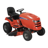
Figure C–27. Rod Guide, Brake Rod, & Springs
Rod Guide / Brake Rod
ROD GUIDE SERVICE
The rod guide is installed between the rear of the clutch
rod and the front of the brake rod. The brake rod
extends from the rear of the rod guide to the brake lever
on the transmission (See Figures C–29 through C–32).
1. Remove the cotter pin and washer that secure the
rear end of the clutch rod to the idler arm and front
end of the rod guide (See Figures C–11 through C-
13).
2. Slip the brake arm spring off the rear portion of the
rod guide (Figure C–27).
3. Remove the hex lock nut from the threaded end of
the brake rod (Figure C–27), and remove the spring
and rod guide .
4. Inspect the rod guide and springs for wear or dam-
age. If no additional service in this area is to be per-
formed, replace as required, reassembling in reverse
order of disassembly. If brake rod service is
required, proceed to next section.
5. Adjust tension on brake rod spring by turning hex
lock nut - with parking brake applied. See Brake
Spring: Aproximate Compressed Lengths on the first
page of this section.
BRAKE ROD SERVICE
The brake rod operates the brake lever on the transmis-
sion and is actuated by movement of the brake pedal/
clutch rod/rod guide linkage (See Figures C–29 through
C–32).
1. Remove the cotter pin and washer that secure the
rear end of the clutch rod to the idler arm and front
end of the rod guide (See Figures C–23 through C-
32).
2. Slip the brake arm spring off the rear portion of the
rod guide (Figure C–27).
3. Remove the hex lock nut from the threaded end of
the brake rod (Figure C–27), and remove the spring
and rod guide .
4. Remove the cotter pin and washer that secures the
rear of the brake rod to the brake lever on the trans-
mission (Figure C–28), and disengage the brake rod
from the brake lever.
5. Inspect the brake rod for wear, corrosion, or other
damage, and replace if required.
6. Reassemble parts in reverse order of disassembly,
and adjust tension on brake rod spring by turning hex
lock nut - with parking brake applied. See Brake
Spring: Aproximate Compressed Lengths on the first
page of this section.
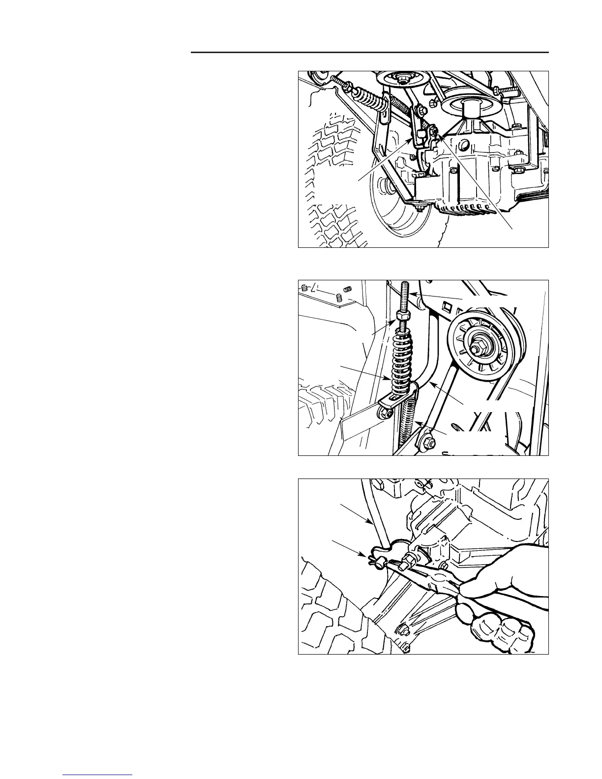
Figure C–28. Remove Brake Rod Cotter Pin
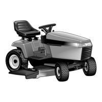
Figure 4C–26 . Hydro Trans Brake Lever & Speed
Selector Lever
Hex Lock Nut
Brake Arm
Spring
Brake
Rod
Spring
Brake Rod
Rod Guide
Cotter Pin
Brake
Rod
Brake Lever
Speed
Selector
Lever