Chapter 1: Hardware overview 15
Callout Component Description
7 Power button Controls power to the server and
indicates whether there is power to the
enclosure. If the indicator is green, the
enclosure is receiving power.
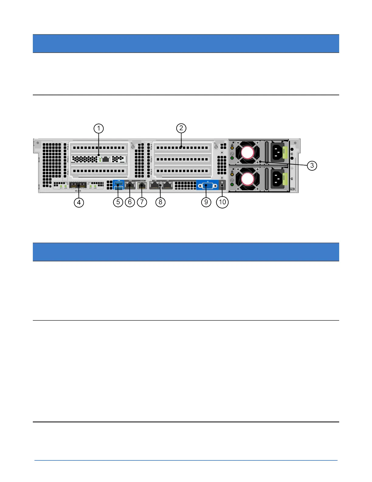
About the back panel components
The following image and table describe the back panel of a UCS C240 M4SX server.
Figure 2: Back panel components
Table 4: Back panel component descriptions
Callout Component Description
1 Accelerator Accelerator in slot PCIe 2, but also
consumes the space in slot PCIe
1. Both indicator LEDs glow solid
green continuously to indicate normal
operation. Flashing LEDs or LEDs that
are yellow or red indicate an error.
2 PCIe riser 2 Slots 4, 5, 6. Optional VIC or VDI cards
can ONLY be installed in slot 5. Slot 5
is the GPU capable slot.
Optional NIC cards can be installed in
slot 4 or 6, and if a VIC is not present,
slot 5 can also be used to install an
optional NIC.
A server with a single CPU does not
contain riser 2. A plate is installed in
place of riser 2.