CR40/42/50 MKII Installation manual Chapter 9
130
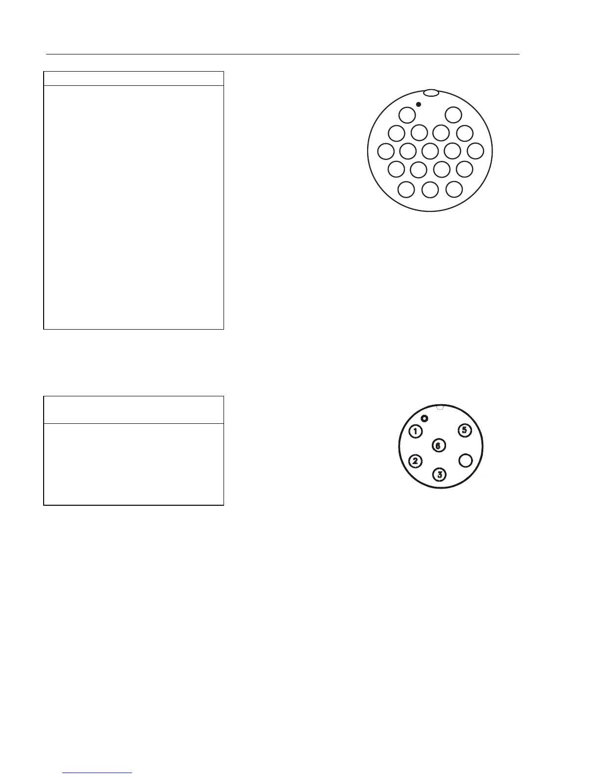
RADAR
1: +250V, Violet
2: +24V, Blue
3: +12V, Orange thick
4: GND, Yellow
5: DATA RETURN, Red shield
6: DATA, Red center
7: N.C.
8: BP/SHF, Brown center
9: BP/SHF RETURN, Brown shield
10:V/TRG, Coax center
11:N.C.
12:BAT+, Red thick
13:N.C.
14:V/TRG RETURN, Coax shield
15:BAT-, Green thick
16:BAT+, Yellow thick
17:N.C.
18:BAT-, Blue thick
Receptacle next to antenna
connection ‘ANT’
1:12V/5mA, White
2:GND, Brown
3:NC
4:12V/1.2A, Green
5:250V/40mA, Yellow
6:24V/20mA, Grey
9.7.1 Power supply connections - (refer to section 9.4)
The internal voltage regulator will allow the CRXX to operate normally over the
power supply voltage range from 10 to 32 Vdc. Connection between the CRXX
and the external power supply is accomplished by means of the supplied power
cable, which is approximately 1.5 meters long, and are not extendable.
After connecting the cable to the power source, push the plug as far as it will go
into the three pin receptacle marked “PWR” on the rear of the cabinet and turn
the plug’s coupling ring clockwise until it makes a click.
) Radar connection cables to
scanners – see section 9.9.3.
Pin numbers and wire colors,
see section 9.9.4.
 Loading...