90 |
Appendix A | V5035 Operator and Installation Manual
Appendix A
IEC 61162-2 Data Interface
The V5035 Class A AIS Transponder provides 2 types of IEC 61162-2
data interfaces for user applications. The first interface type includes
3 input-only sensor data ports and the second interface type
includes 4 bidirectional input/output ports. Data port for each inter-
face type will be described in the following section below.
Sensor Data Input Ports
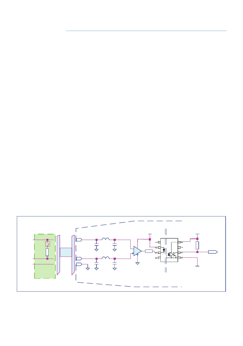
The schematic of input-only sensor data port is shown in Figure A1.
The schematic includes a standard V.11 transceiver IC (Texas Instru-
ments SN65176B) combined with high speed photocoupler which
are used as the main components to receive external data. The
transceiver IC is isolated from external input. To avoid signal reflec-
tion, the transceiver IC has an optional built-in 120Ω loop termina-
tion, which is selectable by the dip-switch on the junction box and
the switch should be set to on position when connecting external
data source with long cable. All sensor data-input ports are isolated
from one another and are also isolated from internal power supply.
The input impedance on A/B wires is greater than 12 KΩ and the
levels on the A/B wires are defined in the following:
Logic low input: A-B < -0.2V
Logic high input: A-B > +0.2V
1K
3V3
System Ground
Isolated Ground
1K
A
B
TGND TGND
120
A
B
TGND
Junction Box
Cable
Rx
Isolated
Main Unit
To
system
Data
Input
V5T
Schematic of sensor data input port.