16
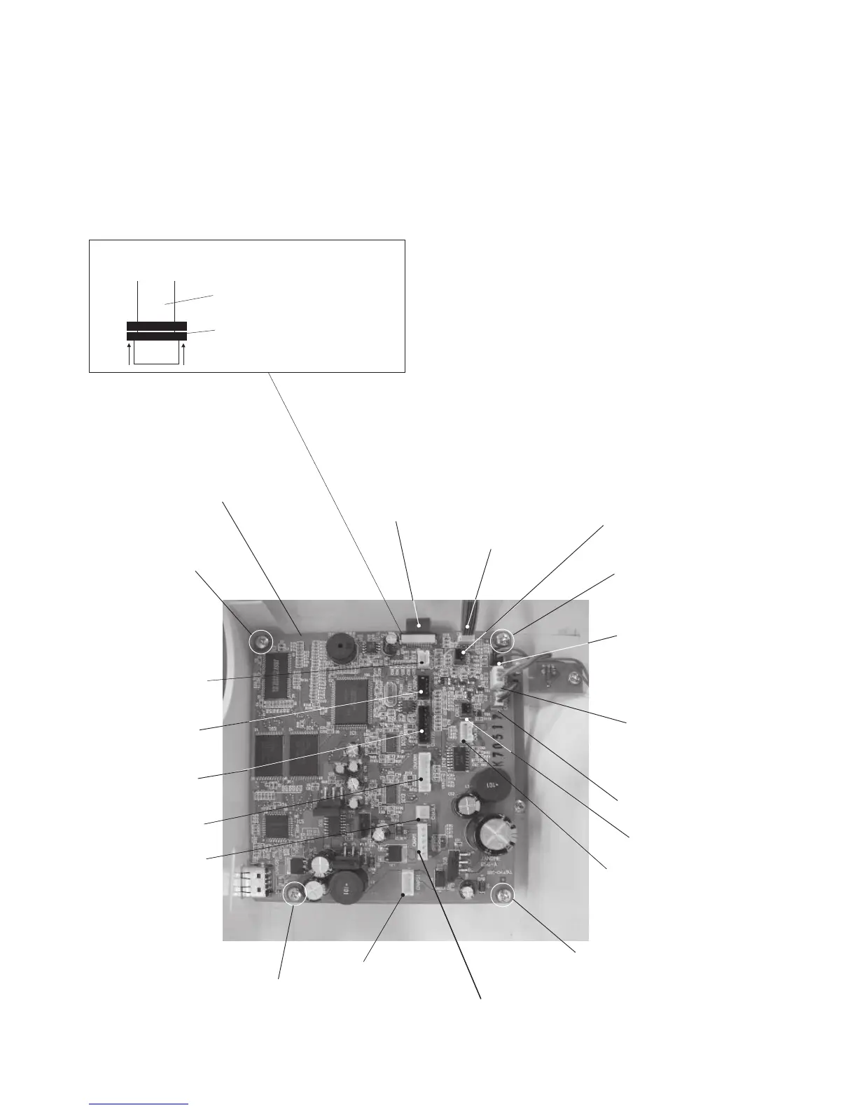
Replacing the Printed Circuit Board A
Printed circuit board A
Setscrew
Touch panel (white)
LCD module (white)
LCD brightness
control (white)
LCD module (green)
LED lamp (red)
Thread detection
sensor (white)
Setscrew
DC motor (white)
Switching power
supply (white)
Setscrew
Setscrew
Presser foot
lifter sensor
(white)
Upper shaft sensor
(black)
Y-motor (black)
X-motor (white)
Tension solenoid
(white)
Bobbin winder switch (blue)
To remove:
1. Remove the face cover, bed cover and front
cover.
2. Disconnect all the connectors from the printed
circuit board A.
3. Remove the 4 setscrews and remove the printed
circuit board A.
To attach:
4. Follow the above procedure in reverse.
NOTE:
Refer to the following diagram when connecting the
connectors.
Printed circuit board F
(black)
Disconnecting LCD Module Flexible
PCB
Flexible PCB
Lift up the clamp to unlock.