In the example above the equipment to be commissioned is:
• Installed across two machines
• Each with two sub-machines
• There are two sensors to be commissioned
• A gateway and a relay node
From the commissioning progress screen, by selecting Sensors, it is possible to ‘drill
down’ through functional locations, then sub-machines to the sensor names and
similarly for the relay node to confirm its name and associated gateway.
3.2 SKF Enlight Collect gateway
3.2.1 Introduction
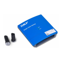
When selecting a location for the gateway choose somewhere central to its
associated sensors and where power and any required network connections can be
made available to it.
Cable connections to the gateway, such as for incoming DC power and Ethernet
cabling, are made in the lower part of the enclosure. To access this area, remove
only the two retaining screws holding the lower cover.
With the lower cover removed, incoming cabling can be terminated at the available
connectors. A blanking plug provides access to a micro SIM card holder. The SIM
card holder is for future use as a mobile data connection is not currently supported.
Important safety warning:
With each gateway SKF provide one 1.5 m power supply connector/cable assembly
and one 1 m connector/cable assembly for the hard-wired Ethernet connection.
Only remove the blanking plug when it is necessary to access the SIM card
holder. Otherwise ensure the blanking plug remains in place.

 Loading...