SECTION 3, Page 1
SJ-600 Series Engine Powered 112715
June 2001
3
SECTION 3
SYSTEM COMPONENT IDENTIFICATION
AND SCHEMATICS
TABLE OF CONTENTS
SYMBOLS & CHARTS
FIGURE 3.1-1. RELAY TERMINAL FUNCTION IDENTIFICATION ...................................................................... 2
FIGURE 3.1-2. ELECTRICAL SYMBOL CHART .................................................................................................. 3
FIGURE 3.1-3. HYDRAULIC SYMBOL CHART ................................................................................................... 4
HYDRAULIC SYSTEM
FIGURE 3.2-1. HYDRAULIC SCHEMATIC Powered Extension Platform ........................................................... 5
FIGURE 3.2-2. HYDRAULIC SCHEMATIC .......................................................................................................... 6
FIGURE 3.2-3. HYDRAULIC MANIFOLD Component and Port Identification ................................................... 8
ELECTRICAL DIAGRAMS
FIGURE 3.4-1. ELECTRICAL PARTS LIST ........................................................................................................ 27
CONTROL BOXES
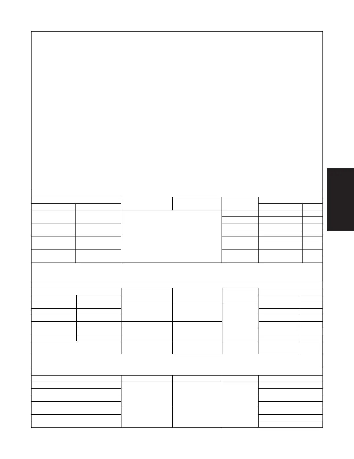
ELECTRICAL SCHEMATIC REFERENCE TABLE
Serial Range Model Engine Options Schematic Location
31801 & Below Figure 3.5-1.
31802 to 33047 Figure 3.5-2.
33048 to 33467 Figure 3.5-5.
33468 & Above
ANSI/SIA & CSA Kubota Dual Fuel
Figure 3.5-7.
33047 & Below Figure 3.5-3.
33048 to 33467 Figure 3.5-6.
33468 & Above
CE Kubota Diesel
All Options
Figure 3.5-8.
PANEL DIAGRAM REFERENCE TABLE
Serial Range Diagram Location
From To
Model Engine Options
Figure
Page
Below 30985 Figure 3.4-2.
31
30986 32097 Figure 3.4-3.
32
32098 Above
ANSI & CSA Kubota Dual Fuel
Figure 3.4-4.
33
Below 30985 Figure 3.4-5.
34
30986 32097 Figure 3.4-6.
35
32098 Above
CE Kubota Diesel
All Options
Figure 3.4-7.
36
Current Production ANSI, CSA & CE Both
Electrical
Inverter
Figure 3.4-8.
37
LARGE PULL-OUT ELECTRICAL SCHEMATICS
CONTROL BOX REFERENCE TABLE
Serial Range Diagram Location
From To
Model Engine Options
Figure Page
No Options Figure 3.3-1A. 10
Below 32097
All Options Figure 3.3-2A. 18
No Options Figure 3.3-1B. 12
32098 33047
All Options Figure 3.3-2B. 20
No Options Figure 3.3-1C. 14
33048 33188
All Options Figure 3.3-2C. 22
No Options Figure 3.3-1D. 16
33189 Above
ANSI/SIA & CSA W/Ford Dual Fuel
And CE W/Kubota Diesel
All Options Figure 3.3-2D. 24
ELECTRICAL PANEL DIAGRAMS