Page 50 December 2007
ZB2044
Procedures Section 2 - Operation
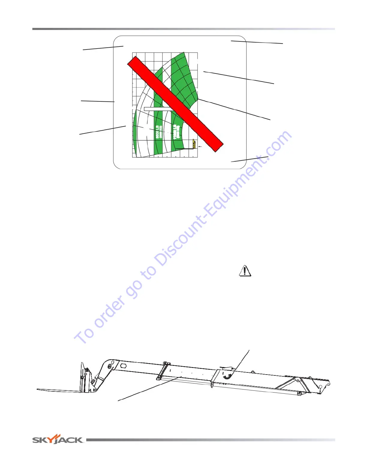
2.12 Use of the Capacity Charts
The capacity charts are located in the operator’s cab.
They are used to determine maximum load capacity
for telehandler equipped with different attachment
combinations.
To properly use a particular capacity chart, the operator
must rst determine the following:
1. Ensure the capacity chart is for the specific
telehandler model and the attachment.
2. Determine the weight of the load to be lifted.
3. Determine the height where the load is to be
picked or placed.
4. Determine the reach where the load is to be picked
or placed.
5. The maximum capacity is determined by the
intersection lines between height and reach on
the capacity chart. If the intersection of the lines
occurs at a division between capacity zones, the
smaller of the two capacity values must be used.
NOTE
The weight of the load must be equal to or
less than the number in the capacity zone.
WARNING
When handling load, ensure that boom
extension indicators and boom angle
indicator remain within previously
determined/calculated capacity zone.
Capacity Chart
Telehandler
Model
Telehandler
Attachment
Boom
Extension
NO LIFT ZONE
FORWARD
REACH
LOAD RATINGS COMPLY WITH
ANSI/ITSDF B56.6 - 2005
STABILITY REQUIREMENTS FOR
ROUGH TERRAIN FORKLIFTS.
RATED CAPACITY (LB)
AT 48" LOAD CENTRE.
2 3/4" x 6" FORKS
MAXIMUM LOAD LIMTED
BY FORK CAPACITY
CAPACITY CHART MODEL ZB2044
LOAD CHART COVERS INTEGRAL FORK-POSITIONER/SIDE-SHIFT CARRIAGE
NO LIFT ZONE.
NO LOAD BEHIND
FRONT FACE OF TIRE.
ALL DIM. ARE U.S.A.
CUSTOMARY UNITS.
DIM. IN (BRACKETS)
ARE S.I. UNITS.
-11
o
0
o
44
FT
(13.4)
36(11.0)
32(9.8)
28(8.5)
24(7.3)
20(6.1)
16(4.9)
12(3.7)
8(2.4)
4(1.2)
-4(-1.2)
00
40
(12.2)
(M)
H
E
I
G
H
T
WITH OUTRIGGERS
G
C
F
E
D
B
O
O
M
E
X
T
E
N
S
I
O
N
28
(8.5)
24
(7.3)
20
(6.1)
16
(4.9)
12
(3.7)
8
(2.4)
4
(1.2)
0
0
FT
(M)
(4990 KG)
8500 LB
(3860 KG)
10000 LB
(4540 KG)
11000 LB
(4990 KG)
OUTRIGGERS DOWN
FACE OF TIRE
10
o
20
o
30
o
50
o
60
o
70
o
30
B
6500 LB (2950 KG)
7000 LB
(3175 KG)
SAMPLE ONLY - USE CHART IN CAB
Figure 2-14 Sample Capacity Chart
Height
Boom
Angle
Reach
E
B
C
D
Boom Angle
Indicator
Boom Extension
Indicators
Figure 2-15 Boom Indicators
To order go to Discount-Equipment.com