10
3059
23 2024
-
PJC 221 & 222
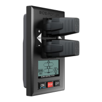
PDC 101
(SAC Controller) (This device is not able to edit. Pre-setup from factory.)
PDC 101 must be setup by authorized personnel.
Firmware version and serial number is Not Available (NA).
Location
Values: BOW/STERN/BOW-STB/STERN-STB
BOW or STERN in a conventional thruster system.
In a system with two bow or stern thrusters (i.e a catamaran),
BOW and STERN is port thruster, BOW-STB and STERN-STB
is starboard thruster.
(NB: If the boat has Sleipner stabilizer and AC or DC thrusters the thruster location should be set as BOW-STB
or STERN-STB. This so the hydraulic controller are shown at the left side in display and thruster(s) at the right
side of the display.)
Direction
Values: NA (Not Available)
AC System - PDC 101 Setup
AC System - PDC 201 Setup
MC_0096
MC_0096
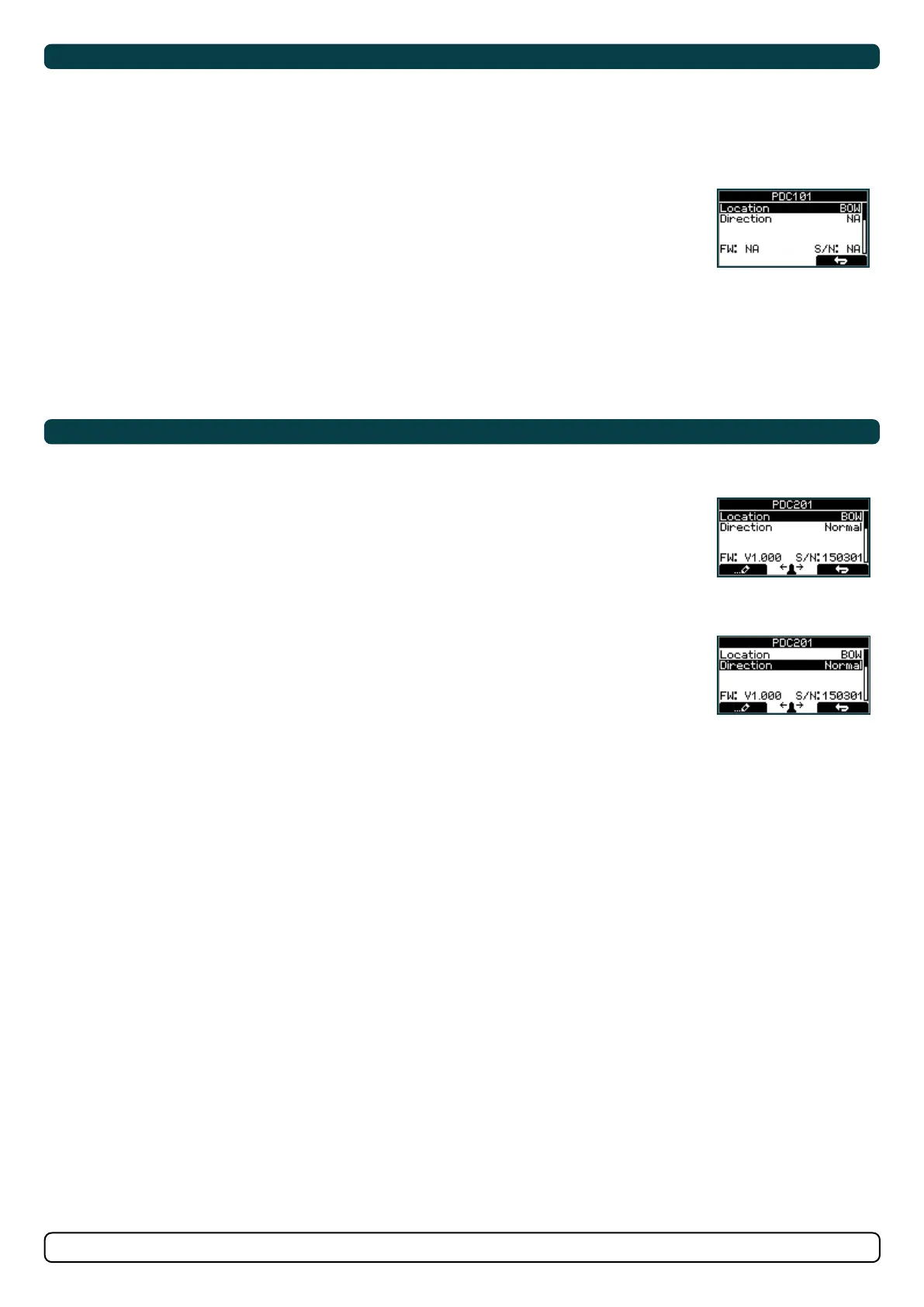
PDC 201
Location
Values: BOW/STERN/BOW-STB/STERN-STB
Set the location for selected device. Use BOW or STERN in a conven tional thruster system. In a system
with two bow or stern thrusters (i.e a catamaran), use BOW or STERN for port thruster, BOW-STB or
STERN-STB for starboard thruster.
(NB: If the boat has Sleipner stabilizer and AC or DC thrusters the thruster location should be set as
BOW-STB or STERN-STB. This so the hydraulic controller are shown at the left side in display and
thruster(s) at the right side of the display.)
Direction
Values: Normal (default)/Inverted
Switches between Normal and Inverted
running direction for the thruster.
5.0
5.1
5.2
6.0
6.1
6.2
AC System - PDC-301 Setup
MC_0096
PDC-301 - Controller for AC thrusters
Firmware version and S-Link serial number are displayed at the bottom of the confi guration menu.
Location
Values: BOW/STERN/BOW-STB/STERN-STB
Set the location for selected device. Use BOW or STERN in a conventional thruster system. In a system
with two bow or stern thrusters e.g. a catamaran, use BOW or STERN for port thruster, BOW-STB or
STERN-STB for starboard thruster.
If the boat has Sleipner hydraulic stabilizer and AC thrusters the thruster location should be set as
BOW-STB or STERN-STB. Then the hydraulic controller is shown at the left side in the display and
thruster(s) at the right side of the display.
Direction
Values: Normal (default)/Inverted
Switches between Normal and Inverted running direction for the thruster. If the direction of thrust
is opposite of the direction of movement of the joystick this parameter can be used to align thrust
direction with the operation of the joystick.
Function
Values: SAC (default), SRAC
Setup the control unit behaviour.
-SAC: Tunnel thruster
-SRAC: SAC retractable thruster. SR150000 retractable controller must be set as SRHP/SRAC.
Max output
Values: 50% to 100% (Default 100%)
Set the maximum output thrust of PDC-301 in percent. PDC-301 will scale the input signal to this value.
Load share limit
Values: 0% to 100% (Default 100%)
The Load Sharing limitation allows the system to limit the combined load on the generator from a bow
and stern thruster when both thrusters are used at the same time. The load sharing will dynamically
limit the thrust request for each thruster depending on the joystick position and limit settings.
See AC series thruster user manual (document ID 6054) for a detailed explanation and setup guide.
Drive Type
Values: ACS580 (default), VACON
Select the type of Variable Frequency Drive (VFD) to be controlled by PDC-301. Select ACS580 if the
drive is an ABB ACS580 or ACS880.
Asymmetric Thrust
Values: 0% to 100% (Default 100%)
This setting can be used to improve performance of dual bow or stern thruster installations such as
those found on catamarans or vessels with stern drive units. Pushing water at high flow into an adjacent
tunnel may result in cavitation and reduction of thrust for the nearby tunnel.
Pushing water towards the drive unit, above a certain flow rate, might not further increase the
thrust. Thus for vessels with stern drive and dual thruster installation the current consumption could
potentially be improved by reducing flow towards the drive unit while not reducing maximum achieved
thrust.
The Asymmetric Thrust value limits maximum thrust in one direction. The limiting direction is
determined by the Location setting of the thruster.
Thrusters with Location set to BOW or STERN will limit thrust towards port side and hence reduce the
water flow towards starboard.
Thrusters with Location set to BOW-STB/STERN-STB will limit thrust towards starboard side and hence
reduce the water flow towards port.