17
3059
23 2024
-
PJC 221 & 222
Hold Calibration
Menu System Information
Information - PPC, SR150000, SR61242
Joystick Calibration
MC_0098
MC_0098
MC_0098
MC_0098
Setup
Default in systems
without stabilizers
Calibrates the HOLD-function to get balanced thrust from the bow and stern thruster. If only one
thruster or PJC221/PJC211 you will not get any balanced thrust, but you can adjust the maximum
thrust from HOLD buttons. Hold-button represents 1/6 of the calibrated value.
(NB: HOLD CALIBRATION is not available until SETUP is completed.)
To start calibration, press the “+”-Hold button in the desired direction. For a fi rst time calibration, the thrusters
will start at 70%. A system previously calibrated will start with the last amount of thrust set.
Adjust power with the joystick.
Press the button below to save the calibration values.
Press the button below to cancel calibration without saving.
(NB: Setup calibration in one direction sets values for both directions.)
THRUSTER INFO
Display info about the thrusters in the system.
The number of thrusters/controllers found is
shown in the upper right corner of the display.
The list of devices found can fi ll more than one screen. A scroll bar indicates the position of the selected item.
The joystick(s) operates the thrusters as normal while info is displayed. This will be useful for troubleshooting,
service and general system diagnostics. List will only show devices present on the S-link.
PPC DC Speed Controller
SR150000 Retract controller
SR61242 Retract controller
Motor Temp: Temperature measured at the electric motor brushes
(Not implemented in SR61242)
Contr. Temp: Temperature measured inside the controller
(Not implemented in SR61242)
Voltage: Motor Voltage measured at the controller
Thrust: Thrust level from joystick/hold buttons
°/A/kW: Retract angle (SR150000) / Motor Current (PPC) / Power reading (PPC). SR150000 retract angel is 0°
when fully deployed, and about 90° when retracted. Put SR150000 in service mode and operate the
controller manually in an out to read the two end position angels for service and installation.
(only for PJC2xx panels with HW V2)
This function is for calibrating the joysticks, and requires a pin code to enter. This option is for service personnel
only.
INFO
• Move between menu items with the (stern) joystick.
• Press the button below to select the highlighted menu entry.
• Press the button below to return to the previous menu.
Information - PDC 101 & PDC 201
MC_0098
MC_0098
MC_0098
PDC 101 and PDC 201 (Controller for AC electric thrusters)
Motor Speed: RPM on motor output shaft
Motor Power: Motor power consumption in % (PDC 201 only)
Motor Temp: Temperature measured in motor
Thrust: Thrust level from joystick/hold buttons
PDC-301 (SAC controller)
Motor : speed (rpm), temperature (°C/°F), power (kW), AC current (A) & AC voltage (V).
Thrust: Joystick thrust (%)
eVision and EHP
At the top: eVision Product Number e.g. E210C-48V and Instance e.g. BOW
Power feed: Input Voltage and Motor Current
Speed: Motor speed in RPM
Thrust: Output thrust in % Load: Motor Load in % of nominal torque
Stator: Temperature Inverter: Temperature
Information - PDC-301
Information - eVision & EHP
Information - PHC-3 & PHC024
MC_0099
PHC-3 and PHC024 (Controller for hydraulic thrusters)
Oil Pressure: Oil pressure measured at system oil tank
Oil Temp: Temperature measured inside the oil tank
Bow Thrust: Thrust level from joystick/hold buttons
Stern Thrust: Thrust level from joystick/hold buttons
FW: Version number, Firmware
S/N: Serial number of the PHC
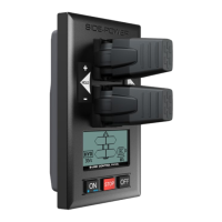
Panel Information
MC_0100
Display info about the control panel
FW: Version number, Firmware
HW: Version number, Hardware
S/N: Serial number of the control panel
Voltage: S-link system voltage measured at the panel
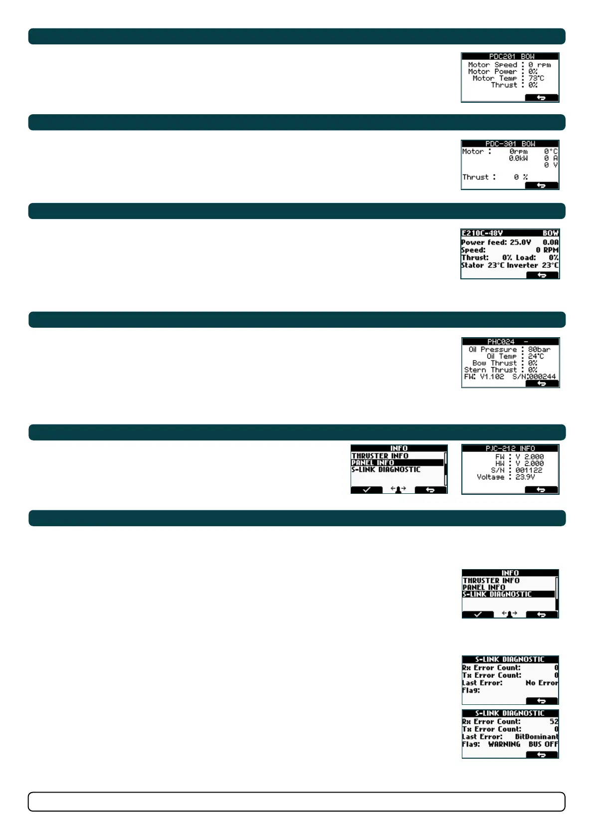
• Shows live update of S-link bus (CAN-bus) error status for the panel.
• Showing no error and signal condition is good.
• Example showing lots of error and very bad signal conditions.
DIAGNOSTIC DISPLAY
Rx Error Count
Receive error counter. Error during reception increments the value. After every successful reception the
value is decremented.
Tx Error Count
Transmit error counter. Error during transmit increments the value. After every successful transmit the
value is decremented.
Last Error
Indicates the error condition of the last error detected. If a message has been transferred or received
without error, it will show No Error.
Conditions: No Error, STUFF, FORM, ACK(Acknowledgment), BitRecessive, BitDominant & CRC.
Flag
BUS OFF: when Tx Error Count is greater than 255 and overflowed. (Tx Error Count will show 0 when in
BUS OFF state)
WARNING: when Rx Error Count or Tx Error Count has reached 96 counts
PASSIVE: when Rx Error Count or Tx Error Count is more than 127 counts
(NB: When S-link devices are hot plugged or disconnected to the bus or powered (when AMS is engaged
and powering PPC and retract), it is not unusual to see some values been incremented. But they will
quickly decrement to 0 again. This will not cause any communication issues.)
S-Link Diagnostic
MC_0100