13
3059
23 2024
-
PJC 221 & 222
10.0
10.1
10.2
10.3
10.4
9.6
9.7
DC System - Automatic Main Switch Setup
DC System - PPC Setup
MC_0097
MC_0097
Main Switch
Location
Values: BOW/STERN/BOW-STB/STERN-STB
Set the location for selected device. Use BOW or STERN in a conventional thruster system. In a system
with two bow or stern thrusters (i.e a catamaran), use BOW or STERN for port thruster, BOW-STB or
STERN-STB for starboard thruster.
(NB: If the boat has Sleipner hydraulic stabilizer and DC thrusters the thruster location should be set
as BOW-STB or STERN-STB. This so the hydraulic controller are shown at the left side in display and
thruster(s) at the right side of the display.)
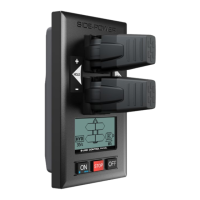
PPC - DC Speed Controller PPC520 / PPC800 / PPC820/ PPC840
The Proportional Power Controller models PPC520, PPC800, PPC820 and PPC840 have the same
confi gurable parameters. Firmware version and S-Link serial number are displayed at the bottom
of the confi guration menu.
Location
Values: BOW (default), STERN, BOW-STB, STERN-STB
Set the location for selected device. Use BOW or STERN in a conventional thruster system. In a
system with two bow or stern thrusters, e.g. a catamaran, use BOW or STERN for port thruster,
BOW-STB or STERN-STB for starboard thruster.
If the vessel has Sleipner hydraulic stabilizer installed and DC thrusters the thruster location should be
set as BOW-STB or STERN-STB. This ensures that the hydraulic controller is shown at the left side in the
display and thruster(s) at the right side of the display.
Direction
Values: Normal (default)/Inverted
Switches between Normal and Inverted running direction for the thruster. If the direction of thrust
is opposite of the direction of movement of the joystick this parameter can be used to align thrust
direction with the operation of the joystick.
For SRVP/SRLP retract installations Direction must be confi gured in the SR150000 for the direction
change to take effect.
Function
Values: SEP (default), SRP, SRVP/SRLP
Confi gure thruster type.
- SEP: Tunnel speed thruster, PPC without retract.
- SRP: Retract SR61242 with PPC, both devices need to be set to SRP.
- SRVP/SRLP: Retract SR150000 with PPC, both devices need to be set to SRVP/SRLP.
Max output
Values: 50%-100% (default 100%)
Limits maximum thrust according to the configured value.
The thruster will linearly scale the joystick signal to the configured Max Output.
Applies for PPC800 from V1.022
Applies for PPC520/PPC820/PPC840 from V1.008
Thermo Switch
Values: Disable (default), Enable
Disable or Enables the thermo switch input on the PPC.
The thermo switch is normally closed and opens at high temperature.
On PPC520/PPC820/PPC840, if the thermo switch input is connected to GND at power-up then this
parameter is automatically set to Enable.
Applies only for PPC520/PPC820/PPC840 from V1.016
DC System - PPC Setup
DC System - eVision Setup
MC_0097
MC_0097
Extended runtime
Values: OFF (default), ON
The extended runtime function will increase the thruster’s maximum runtime, by reducing the
maximum thrust when the motor temperature is high. Extended runtime can be used when thruster
runtime needs to be extended, e.g. dynamic positioning- or docking systems.
OFF: Extended runtime function is disabled.
ON: Extended runtime function is enabled.
Applies for PPC520/820/840 from V1.030.
Asymmetric thrust
Values: 0% to 100% (Default 100%)
This setting can be used to improve performance of dual bow or stern thruster installations such as
those found on catamarans or vessels with stern drive units. Pushing water at high flow into an
adjacent tunnel may result in cavitation and reduction of thrust for the nearby tunnel.
Pushing water towards the drive unit, above a certain flow rate, might not further increase the
thrust. Thus for vessels with stern drive and dual thruster installation the current consumption
could potentially be improved by reducing flow towards the drive unit while not reducing maximum
achieved thrust.
The Asymmetric Thrust value limits maximum thrust in one direction. The limiting direction is
determined by the Location setting of the thruster.
Thrusters with Location set to BOW or STERN will limit thrust towards port side and hence reduce
the water flow towards starboard.
Thrusters with Location set to BOW-STB/STERN-STB instance will limit thrust towards starboard
side and hence reduce the water flow towards port.
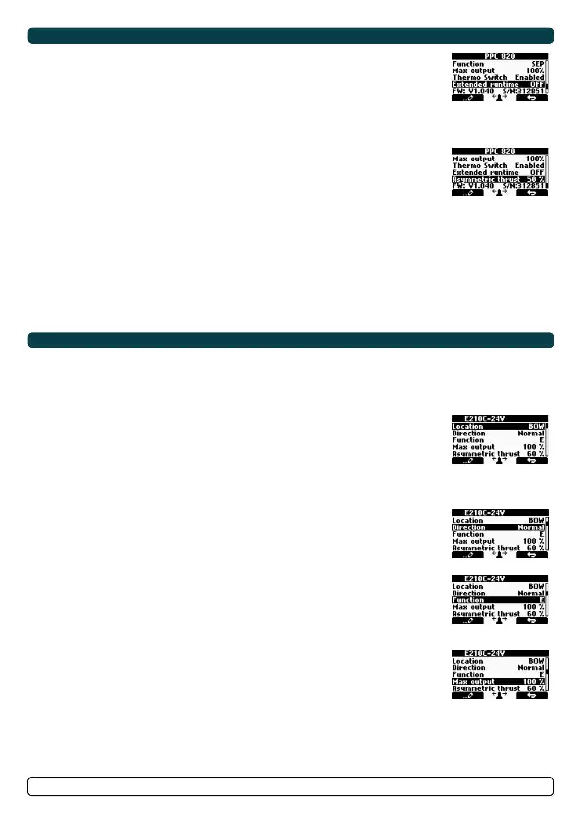
Exxx-xxV - eVision DC proportional thruster
eVision thrusters has several parameters that can be confi gured.
Exxx=thrust in kg
-xxV=operating voltage.
Location
Values: BOW (default), STERN, BOW-STB, STERN-STB
Set the location for selected device. Use BOW or STERN in a conventional thruster system. In a system
with two bow or stern thrusters, e.g. a catamaran, use BOW or STERN for port thruster, BOW-STB or
STERN-STB for starboard thruster.
If the vessel has Sleipner hydrulic stabilizer installed and DC thrusters the thruster location should be
set as BOW-STB or STERN-STB. This ensures that the hydraulic controller is shown at the left side in the
display and thruster(s) at the right side of the display.
Direction
Values: Normal (default)/Inverted
Switches between Normal and Inverted running direction for the thruster. If the direction of thrust
is opposite of the direction of movement of the joystick this parameter can be used to align thrust
direction with the operation of the joystick.
Function
Values: E (default), ERV/ERL
Confi gure thruster type.
- E - Tunnel thruster (default)
- ERV/ERL - Retractable eVision thruster
Max output
Values: 50%-100% (default 100%)
Limits maximum thrust according to the configured value.
The thruster will linearly scale the joystick signal to the configured Max Output.