34
3059
23 2024
-
PJC 221 & 222
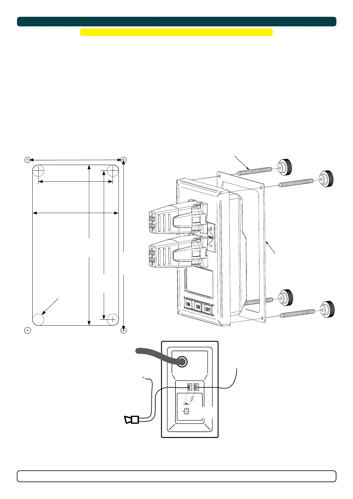
Control Panel Installation
Find a suitable location for the control panel where it does not obstruct or is obstructed by other devices. Install the control panel on a flat surface
where it is easy to use.
1. Use the supplied cut-out template to mark the area to remove on your control dash.
2. Cut out the area per template for the control panel. (NB: If the front surface around your cut out is jagged or chipped, use a sealant
to assist the gasket.)
3. Place the gasket to the back face of the panel
4. Plug cables into the connectors at the rear of the control panel.
5. Insert the control panel in place and fasten screws.
6. Insert the control panels covering caps.
MC_0042
! Please refer to the graphic for special considerations relating to your model !
MG_0063
GASKET
4x SCREWS
58 mm
67 mm
125 mm
116 mm
132.7 mm
75.7 mm
Ø 4.5 mm Ø 4.5 mm
Ø 4.5 mm Ø 4.5 mm
(S-link)
External alarm buzzer
12V / 24V DC - max 0,5A
External alarm / buzzer connection
Supply
+ 12V / 24V DC
-
+
Ø 4.5 mm
Re
a
r
s
i
d
e
o
f
p
a
n
e
l
Internal
fuse / relay
MG_0159
BACKBONE Cable
Forms the communication and power bus throughout
a vessel. Available in different standard lengths.
*Blue ends
*Blue ends
*Blue ends *Blue ends
*Blue ends
*Blue ends
*Blue ends
*Blue ends
*Blue ends
*Green ends *Green ends
*Green ends
*Green ends
*Green ends
SPUR Cable
Used to connect S-Link compliant products to the
backbone cable. One SPUR Cable must be used for
each connected component, with no exceptions.
Recommended to be as short as practically possible.
Available in different standard lengths.
POWER Cable
Required in all installations for connection of BACKBONE
Cable to a power supply and should be protected with a
2A fuse.
4-Port T-Connector
The 4-PORT T-connector allows multiple SPUR Cables to be
connected. The 4-PORT T-connector comes with two sealing
caps to protect unused ports.
T-Connector
Used for connection of SPUR
or POWER Cable to the
BACKBONE Cable. One
T-Connector for each
connected cable.
BACKBONE Extender
Connects two BACKBONE
Cables to extend the length.
END Terminator
Must be one at each end of
the BACKBONE bus.
12/24V
GND
Switch
Optional
Fuse
2A
S-Link installation example
Spur
Power
T-Connector
End
Terminator
End
Terminator
Backbone Extender
Bow Thruster
Control Panel
Spur
Control Panel
Backbone Backbone
Backbone
Spur
Spur
*For DC system
Spur
4 Port T-Connector 4 Port T-Connector
Stern Thruster
Automatic
Main switch
S-Link
Power Supply
Yellow
Red
Black