19
3059
23 2024
-
PJC 221 & 222
Menu System - Panel Setup
MC_0101
PANEL
• Move between parameters with the (stern) joystick.
• Press the button below to return to the previous menu.
• Press the button below to edit the selected parameter.
• Parameter value will start to blink, use joystick to alter value.
• Press the button below to save the edited parameter.
• Press the button below to cancel editing without saving.
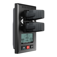
SYSTEM PANEL
BACK LIGHT LEVEL
Values: 1-5
Set level of panel back light in daylight mode.
1 is lowest intensity, 5 is the highest.
BACKLIGHT NIGHT COLOUR
Values: GREEN, BLUE, RED, WHITE
Select colour of back light in night light mode.
BACK LIGHT NIGHT LEVEL
Values: 1-3
Set level of panel back light in daylight mode, 1 is lowest intensity, 3 is the highest.
TIMER AUTO-OFF
Values: OFF, 01-60 min
Set the time from last use to auto panel shut-down. Set from 1-60 minutes in 5 minute steps (1 minute steps
from 1 to 5 minutes) or OFF (panel will not turn off automatically). Values when retract on the boat: 1-30 min.
UNIT TEMPERATURE
Values: CELSIUS (Default), FAHRENHEIT
Set the panel temperature displaying unit.
WHEN RETRACT IS OUT
Values: NO WARNING (Default), WARNING EVERY 10sec
Select ‘WARNING EVERY 10sec’ for external buzzer or lamp warning every 10 seconds when retract is out. This
will activate the internal relay for 0.2 seconds every 10 seconds while the retract is out. See page 26 for buzzer
connections.
RELAY OUTPUT
Values: ALERT LEVEL 1 , ALERT LEVEL 2 , ALERT LEVEL 3 (Default)
ALERT LEVEL 1: When using the HOLD Function the relay output warns if the motor temperature is getting
high or if the voltage is getting low.
ALERT LEVEL 2: The relay output warns for all alarms and warnings in the S-link system only when any device
is sending thrust. Even when the panel is turned OFF.
ALERT LEVEL 3: The relay output warns for all alarms and warnings in the S-link system. Even when the panel
is turned OFF.
See ‘Alarm descriptions’ in “Ext. buzzer activation at Alert Level” column for specifi c alarm action.
PANEL FACING
Values: FORWARD (Default), AFT
FORWARD: Is when panel is facing forward
AFT: Is when panel is facing aft. Display view will rotate 180 degree and joysticks thruster
function will also rotate 180 degree.
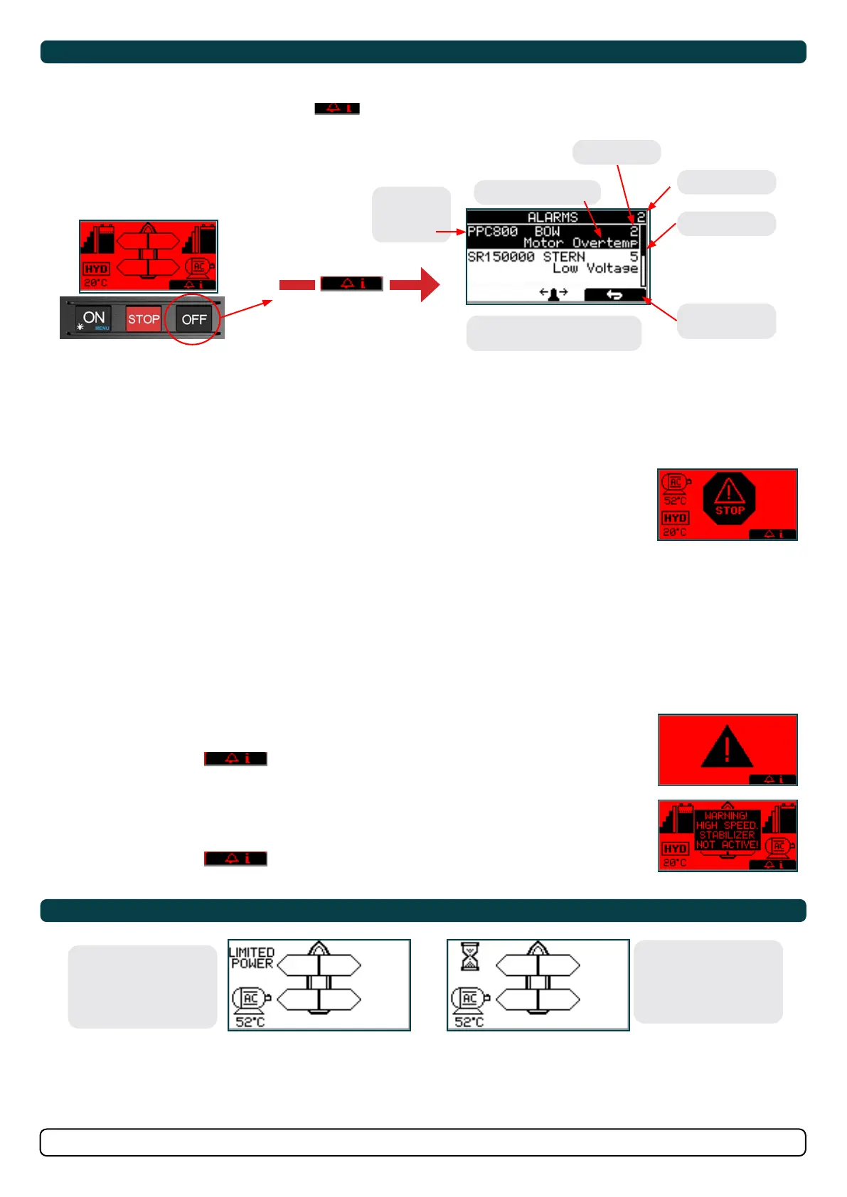
Alarm System
MC_0757
(Button below this symbol
pressed)
No. of alarms
Alarm description
Reset alarm
and Return
Use joystick to scroll if
more than two alarms
Scroll bar
Name and
location of
device
Refer to Alarm Description and Fault Code chapters for full description of the different alarms.
Example PJC 222:
When there is an alarm or a fault, the panel will show this alarm situation by changing LCD display back light to red colour.
The panel will also change to show “Alarm Info” on the bottom of the screen, indicating that by pressing the corresponding button
below, you will get information about what the problem is (examples below).
Entering “Alarm Info” menu will silence the alarm on all PJC221 and PJC222 panels.
Some alarms needs an reset to stop alerting.
Auto Reset
Some alarms are automatically reset when the fault is no longer present.
This means that this alarms don’t need an manual reset action to be removed from the panel display and the audible alert to stop. At ‘Alarm
Description’ pages in the “Auto Reset” column you can see which alarms that are auto reset.
STOP BUTTON
Pressing the STOP button will immediately suspend all thruster and stabilizer operation. The back light
color of the LCD will turn red and a STOP symbol will be displayed.
The operation of thrusters and stabilizers can be resumed by pushing the STOP button again.
Pressing the STOP button with a hydraulic controller connected to the S-Link bus will activate the load
sense dump valve and the oil pressure will be reduced to the standby pressure, which typically is 20 bar.
Reducing to standby pressure will disable thruster operation, but other low consumption
equipment connected to the same hydraulic system might be operable.
The STOP function is supported by the following products with stated FW version or higher:
PHC024 all FW versions
PHC-3 all FW versions
PPC800 FW V1.029
PPC520, PPC820 and PPC840 FW V1.0025
PDC-301 FW V2.013
ALARM SHOWN ON INACTIVE PANELS!
This screen will be shown when any warning/alarm occurs.
Pressing the button below
will mute buzzer alarm at all panels and show the alarm info screen.
WARNING! HIGH SPEED. STABILIZER NOT ACTIVE!
(Only for yachts equipped with a Side-Power Stabilizer system) Warning will show when yacht is driven at
high speed with stabilizer system inactive. Please refer to the Stabilizer ECU manual for speed settings.
Pressing the button below
will mute buzzer alarm at all panels and show the alarm info screen.
Alarm code
SAC Power Management Status
MC_0758
Symbol alternating with AC motor symbol every 1sec.
*For detailed information on SAC power management operation see SAC user manual.
Power Not Available
Power Management System
is preventing the thruster
from operating.
Reduced Power Mode
Thruster output is limited
to 50 % thrust by Power
Management System.