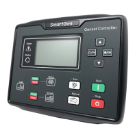
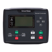
APC615 Pump Unit Controller User Manual
APC615 Pump Unit Controller Version 1.0 2017-10-20 Page 47 of 54
13 CONNECTIONS OF CONTROLLER WITH J1939 ENGINE
13.1 CUMMINS ISB/ISBE
Table 17 – Connector B
Connect with starter coil directly
Expand 30A relay,
battery voltage of
01,07,12,13 is supplied
by relay
ECU power
Auxiliary output port 1 configured as “ECU
power”.
Table 18 – 9 Pins Connector
CAN communication shielding wire (connect to ECU
terminal only)
Using 120Ω impedance connecting wire.
Using 120Ω impedance connecting wire.
Engine type: Cummins ISB
13.2 CUMMINS QSL9
Suitable for CM850 engine control mode
Table 19 – 50 Pins Connector
Connect to starter coil directly
Table 20 – 9 Pins Connector
CAN communication shielding wire (connect to ECU
terminal only)
Using 120Ω impedance connecting wire.
Using 120Ω impedance connecting wire.
Engine type: Cummins-CM850
13.3 CUMMINS QSM11
It is suitable for CM570 engine control module. Engine type is QSM11 G1, QSM11 G2.
Table 21 – C1 Connector
Outside expand relay, when fuel output, making
port 5 and port 8 of C1 be connected
Connect to starter coil directly
Table 22 – 3 Pins Data Link Connector
3 pins data link connector
CAN communication shielding wire (connect to
ECU terminal only)
 Loading...
