EasyManuals Logo
Home>Smartgen>Controller>APC615

Smartgen APC615 User Manual

Smartgen APC615
54 pages
To Next Page IconTo Next Page
To Previous Page IconTo Previous Page
Page #17 background imageLoading...
Page #17 background image
APC615 Pump Unit Controller User Manual
APC615 Pump Unit Controller Version 1.0 2017-10-20 Page 17 of 54
NOTE ECU warning and ECU shutdown illustration: if detailed alarm content displayed on the LCD of
controller, please check engien condition according to the displayed content; otherwise, please look up engine
user manual based on the SPN code to receive information.
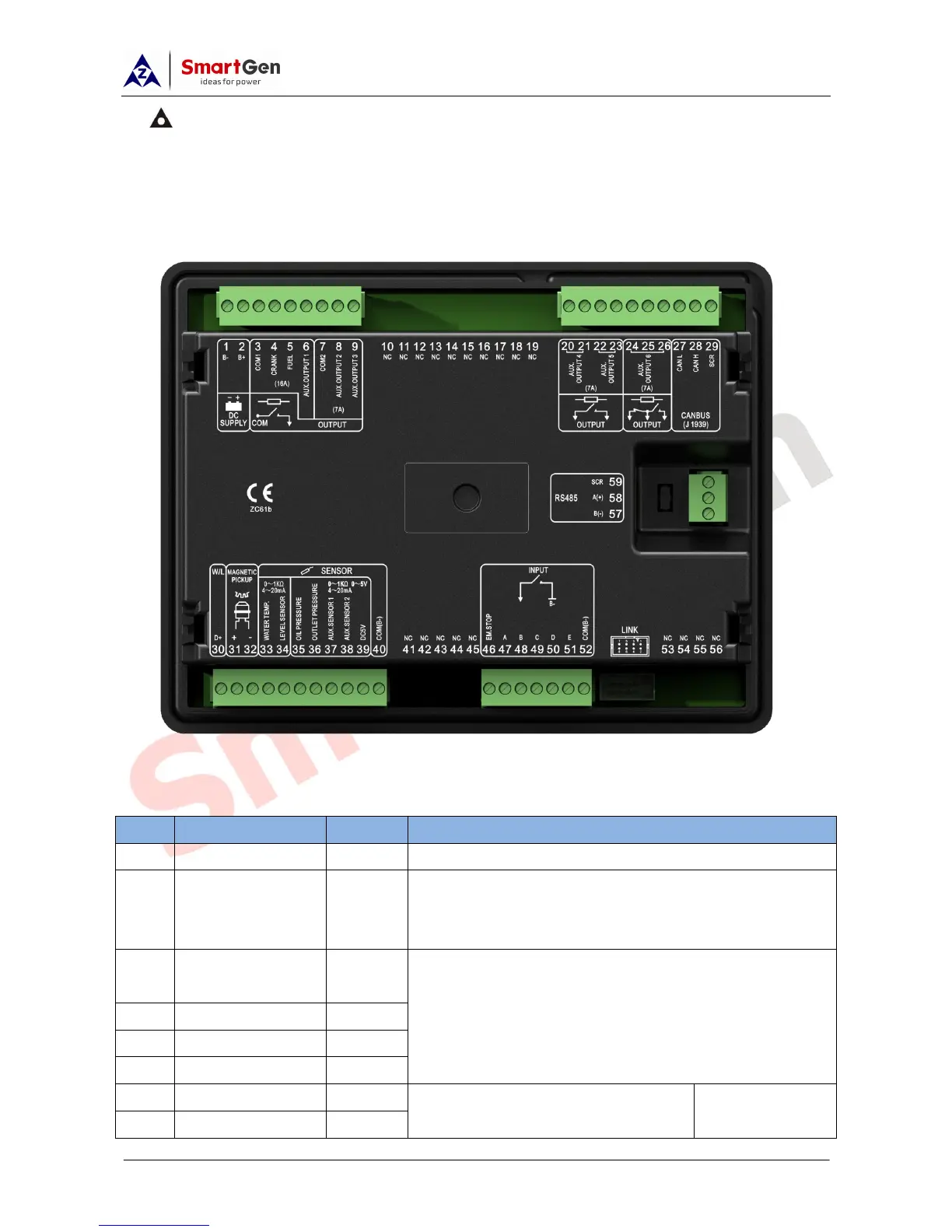
6 CONNECTIONS
Fig. 2 APC615 Back Panel
Description of terminal connections:
No.
Function
Cable Size
Description
1
B-
2.5mm
2
Connected with negative of starter battery.
2
B+
2.5mm
2
Connected with positive of starter battery. If wire length is
over 30m, better to double wires in parallel. Max. 20A fuse is
recommended.
3
COM1 Relay
Common Port
1.5mm
2
Connect to COM1 output with rated 16A.
4
Crank
1.5mm
2
5
Fuel
1.5mm
2
6
Aux. Output 1
1.5mm
2
7
COM2
1.5mm
2
Connect to COM2 output with rated 7A.
Detailed setting
items please to
8
Aux. Output 2
1.5mm
2

Questions and Answers:

Question and Answer IconNeed help?

Do you have a question about the Smartgen APC615 and is the answer not in the manual?

Smartgen APC615 Specifications

General IconGeneral
BrandSmartgen
ModelAPC615
CategoryController
LanguageEnglish

Related product manuals