Alarm
HEC002-A/HEC006-A 9-1
9 Alarm
This chapter explains the various alarms that the product has.
9.1 How to Identify Alarm
The alarm is identified as shown on the following table.
Table9-1 Alarm information
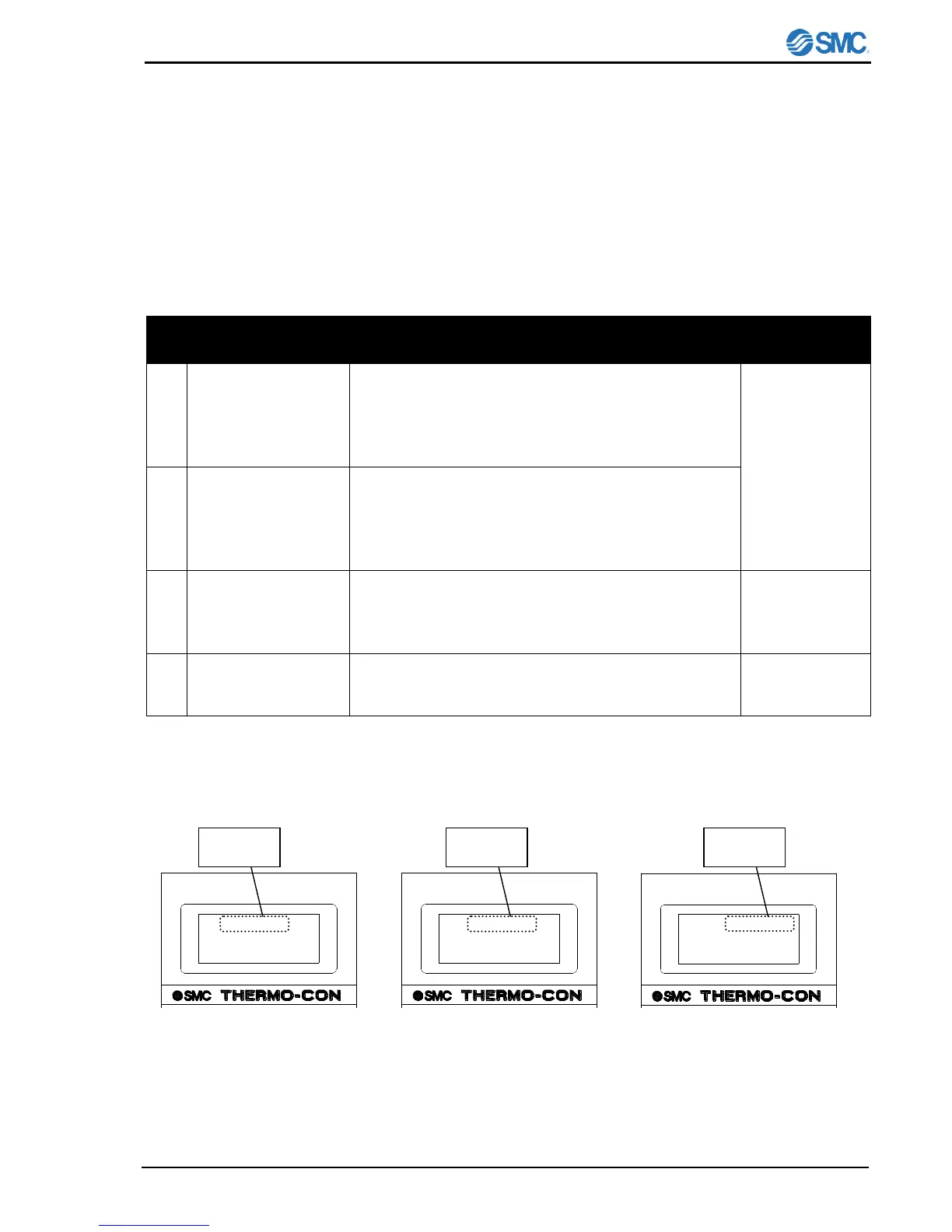
After indication of the software version, the error
No.[ERR**] starts blinking and then a description of the
error is displayed, and [MODE], “Shut Off” is shown.
(“Continuity” is shown instead for ERR15 and ERR18
occurs because the product continues to operate.)
The value of PV and SV disappear and instead, the error
No. [ERR**] starts blinking and the a description of the
error is displayed, and [MODE], “Shut Off” is shown.
(“Continuity” is shown instead when ERR15 and ERR18
occurs because the product continues to operate.)
Even during input of a setting, the error No. [ERR**] starts
blinking on the upper line. After input (pressing [RET] key
to set), a description of the error is displayed (see Fig.9-
1).
Temp. upper/lower
limit alarm occurrence
The value of PV and SV and the indication of [MODE]
remain but also [WRN] lights up. After the error is reset,
the indication of [WRN] disappears
ERR14
Thermostat Alarm
Mode< Shut off
ERR14
PB Range
Mode< 2.0 C
WRN
PV < 26.6 C
SV < 25.0 C
Mode Normal
Fig.9-1 Alarm indication in the
event ERR14 arises
Fig.9-1 Alarm indication in the
event ERR14 arises during PB
range setting input
Fig.9-3 Alarm indication in the
event temp. upper and lower
limit arises

 Loading...