HRX-OM-O021
Chapter 5 Display and setting of various functions
HRS Series 5.18 Communication function
5-55
Communication mode setting and cheking
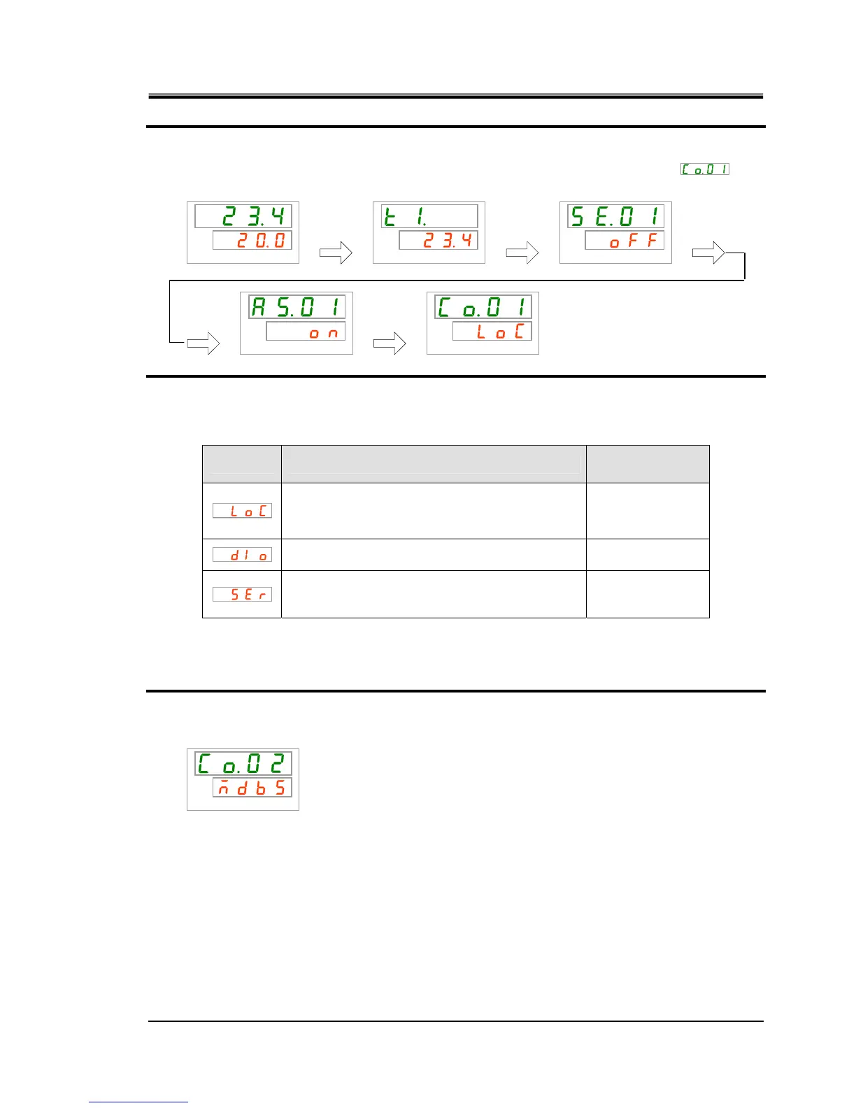
1. Press and hold the [MENU] key for approx. 2 sec.
Repeat pressing the key until the setting screen for communication mode [
]
appears on the digital display.
PV
SV
PV
SV
PV
SV
PV
SV
PV
SV
2. Select communication mode from the table below with [▲] key or [▼] key, and confirm by
pressing “SEL”.
Table 5.18-2 List of set value
Set value Explanation
Initial value
(Default setting)
Sets LOCAL mode.
(The operation panel operates and sets the
thermo-chiller.)
○
Sets DIO mode.
∗
1
(The operation starts with contact input/output.)
Sets SERIAL mode.
∗
2
(Serial communication performs
operation/setting.)
∗1:When the setting of the contact input 1 is “External switch signal”, “DIO mode” cannot be set.
∗2:If the serial protocol is “Simple communication protocol 2” and the contact input 1 is “external
switch signal” or contact input 2 is “remote signal”, “SERIAL mode” cannot be set.
Serial protocol Settinf and checking
3. Press the [SEL] key once.
The set screen of serial protocol is displayed on the digital display.
PV
SV
[MENU]
Press and
hold
[MENU]
Press and
hold
[MENU]
Press and
hold
[MENU]
Press and
hold
[MENU]
Press and
hold
 Loading...


