HRX-OM-O021
Chapter 8 Documents
HRS Series 8.1 Specifications List
8-1
Chapter 8 Documents
8.1 Specifications List
8.1.1 Product specification
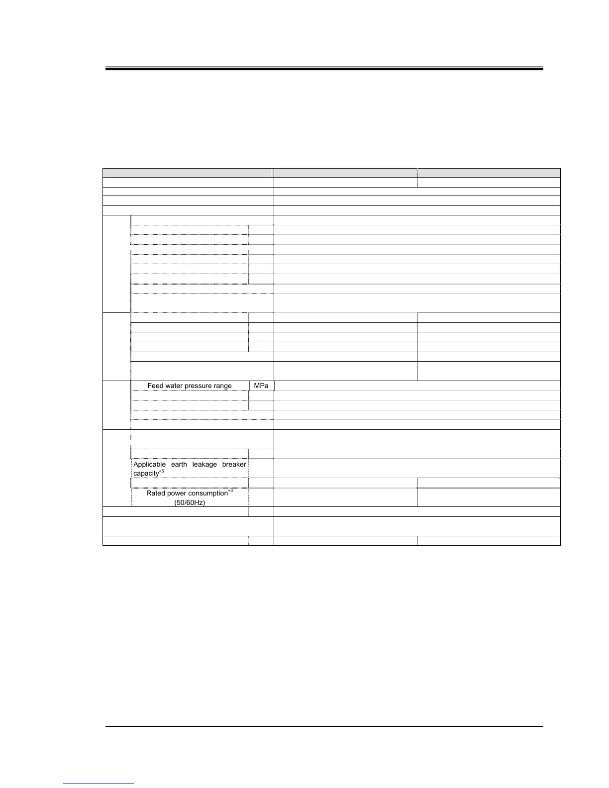
Table 8-1 Specifications List [HRS050-∗∗-20-(BJM)]
Model
HRS050-A∗-20-(BJM) HRS050-W∗-20-(BJM)
Cooling method
Air-Cooled refrigerated type Water-Cooled refrigerated type
Refrigerant R410A (HFC)
Control method PID control
Ambient temperature and humidity
∗2
Temperature :5 to 40
o
C、 Humidity:30 to 70%
Circulating fluid
∗3
Tap water, Ethylene glycol aqueous solution 15%
∗4
Operating temperature range
∗2
o
C 5 to 40
Cooling capacity
∗4
(50/60Hz)
W 4700/5100
Temperature stability
∗6
o
C ±0.1
Pump capacity
∗7
(50/60Hz)
MPa 0.24(at 23L/min)/0.32(at 28L/min)
Rated fiow
∗8
(50/60Hz)
L/min 23/28
Tank capacity L Approx. 5
Port size Rc1/2
Circulating fluid system
Wetted material
Stainless steel, Copper brazing (Heat exchanger)
∗13
, Bronze
∗13
Brass
∗13,
SIC, Carbon, PP, PE, POM, FKM, EPDM, PVC,NBR
Temperature range
o
C
-
5 to 40
Pressure range MPa
-
0.3 to 0.5
Required flow
∗13
L/min
-
16
Facility water pressure differential MPa
-
0.3 more
Port size
-
Rc1/2
Facility water
outlet system
∗15
Wetted material
-
Stainless steel, Copper brazing (Heat
exchanger), Bronze, Synthetic rubber
Feed water pressure range MPa 0.2 to 0.5
Feed water temperature range
o
C 5 to 40
Feed water capacity L/min Approx.1
Automatic fluid filling Port size Rc3/8
Automatic
fluid
filling
∗12
Over flow port Port size Rc3/4
Power supply
AC200 to 230V, 50/60Hz.
Allowable voltage range ±10%
Breaker
∗14
A 20
Applicable earth leakage breaker
capacity
∗5
A 20
Rated operating current
∗3
(50/60Hz)
A 8.0/11.0
7.6/10.0
Electric system
Rated power consumption
∗3
(50/60Hz)
kVA 1.68/2.20 1.55/2.00
Dimensions
∗11
mm W377xD592xH976 (W14.8XD23.3xH38.4[Inch])
Accessory
Sequence I/O command signal connector 1pc., Operation manual (Installatio・Operation)
1pc, Alarm code list label 1pc.
Weight
∗11
kg 69
67
∗1 Use the product in conditions where freezing will not occur.
Consult with SMC if using in a season or region where the ambient temperature will fall below zero.
∗2 If tap water is used, use water which satisfies the standard of The Japan Refregeration And Air Conditioning Industry Association (JRA
GL-02-1994/Cooling water system - circulation type - make-up water)
∗3 (1)Operating ambient temp.: 25
o
C , (2)Circulating fluid temp.: 20
o
C , (3)Circulating fluid rated flow, (4)Criculating fluid : Tap water,
(5) Facilitry water temp.: 25°C(∗15).
∗4 Use a 15% ethylene glycol aqueous solution if operating in a place where the circulating fluid temp. is lower than 10
o
C.
∗5 Outlet temp. when the circulating fluid flow is rated flow, and the circulating fluid outlet and the return are directly connected. Installation
environment and power supply are within specification range and stable.
∗6 The capacity at the thermo-chiller outlet when the circulating fluid temp. is 20°C.
∗7 Fluid flow to maintain the cooling capacity and the temperature stability.
The specification of the coolong capacity and the temperature stability may not be satisfied if the flow rate is lower than the rated flow.
∗8 To be prepared by the customer. Use an earth leakage breaker with sensitivity of 30mA/200V in power
supply specification.
∗9 Front 1m/Height 1m/Static with no load. See note 3 for other conditions.
∗10 Dimension between panels. Projection is not included.
∗11 Weight when the circulating fluid and facility water (for water-cooled type) is not included.
The weight will increase by 1kg when option J [Automatic fluid filling] is selected.
∗12 For option J [Automatic fluid filling port].
∗13 Copper, bronze and brass is not included when option M [DI water piping] is selected.
∗14 In case of option B [Earth leakage breaker], the breaker is changed to an earth leakage breaker.
∗15 For water -cooled type.

 Loading...


