HRX-OM-O021
Chapter 5 Display and setting of various functions
5.21 Option [Electric resistivity sensor set] HRS Series
5-74
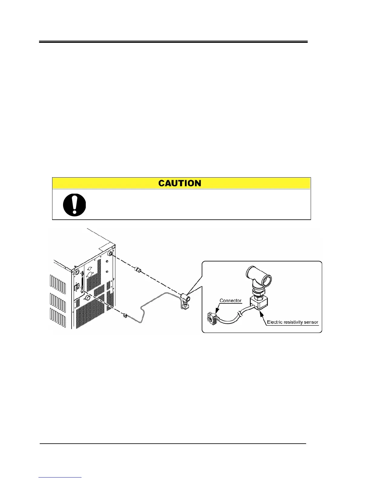
Alarm “AL36 DI sensor failure” must be generated if this setting is
valid with the DI sensor not being connected. Make this setting valid
after installin
.
5.21 Option [Electric resistivity sensor set]
5.21.1 Option [Electric resistivity sensor set]
This function is available for customer who purchased electric resistivity
sensor set (part no.: HRS-DI001). For the installation of the electrical
resistivity sensor set, refer to the Operation Manual of the “Electrical
resistivity sensor set”.
This setting can display the screen of the electric resistivity (Display range: 0
to 4.5MΩ・cm).
By monitoring electric resistivity, alarm [AL34 electric resistivity increase] is
generated when customer’s set value is exceeded, and alarm [AL35 electric
resistivity reduce] when the value is below the customer’s set value.
It is possible to set the operation when the alarm is generated. Refer to the
“5.15 Alarm customize function” for details.
Fig 5.21-1 Option [Electric resistivity sensor set]

 Loading...


