HRX-OM-O021
Chapter 3 Transport and Setting Up
HRS Series 3.7 Wiring of external switch
3-23
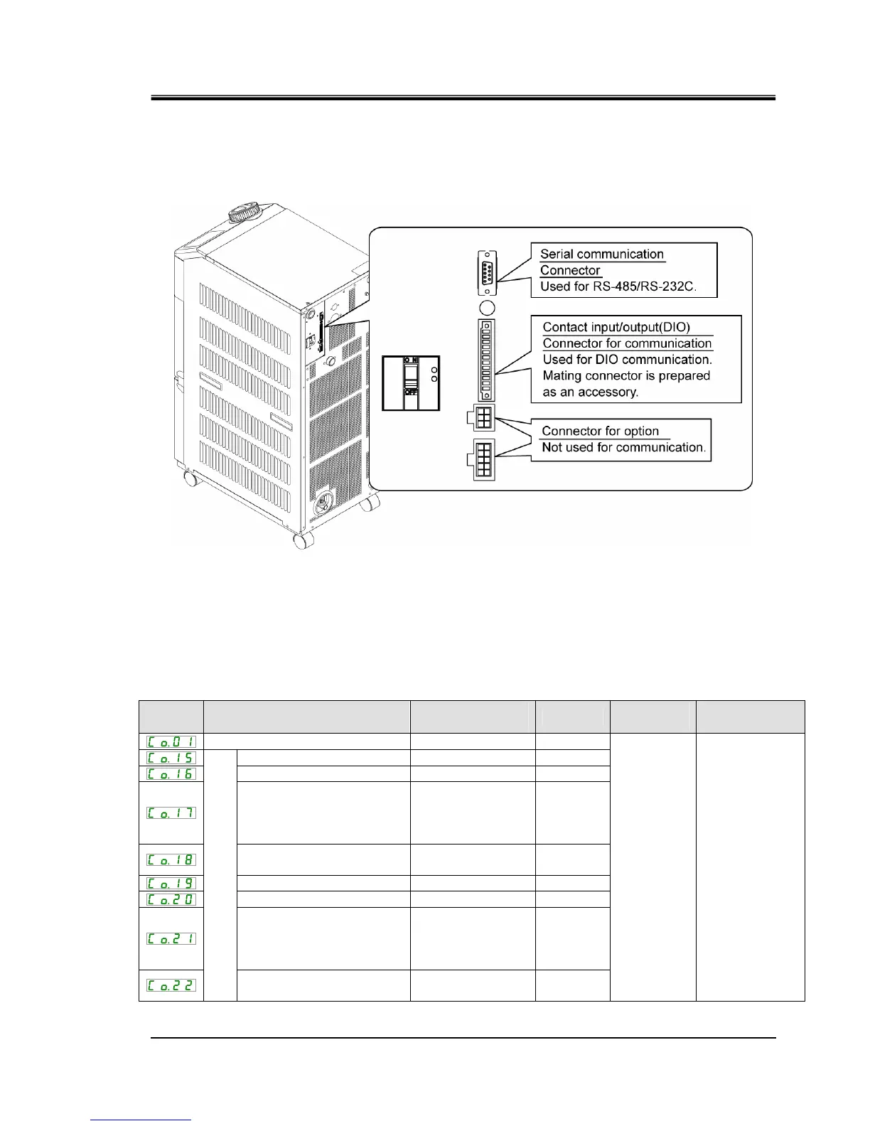
3. Plug the prepared connector in to the contact input/output connector that is on the back
of the thermo-chiller.
Fig 3-19 Connecting the connector
3.7.3 Setting items
Table 3-9 shows the setting items of the external switch. For details, refer to
5.18 Communication function.
Table 3-9 Setting list of the external switch
Display Item
Initial value
(Default setting)
Example
∗
Reference
page
Category
Communication mode LOC LOC
Contact input signal 1 RUN SW_A
Contact input signal 1 type ALT ALT
Contact input signal 1
delay
timer (time delay) of
reading
0 0
Contact input signal 1 OFF
detection timer
0 2
Contact input signal 2 OFF OFF
Contact input signal 2 type ALT -
Contact input signal 2
delay
timer (time delay) of
reading
0 -
Contact input/output communication
Contact input signal 2 OFF
detection timer
0 -
5.18
Communication
setting menu
∗ Example: Connect flow switch A to contact input signal 1 in local mode.
 Loading...


